
DC SERVO MOTOR
PRINCIPLE OF OPERATING
A DC motor is used in a control system where an appreciable amount of shaft power is required. The DC motors are either armature - controlled with fixed field, or field - controlled with fixed armature current. DC motor s used in instrument employ a fixed permanent - magnet field, and the control signal is applied to the armature terminals.
In addition to the torque when conductor moves in magnetic field, voltage is generated across its terminals which opposes the current flow and hence called as Back e.mf.
Basic Classification
Basically d.c. servo motors are classified as:
(i) Variable magnetic flux motors.
(ii)Constant magnetic flux motors
Derivation of transfer functions for
(i) Field controlled d.c. servo motor
(ii)Armature controlled d.c. servo - motors.
i. Field Controlled DC Servo motor Assumptions
(1)Constant armature current is fed into the motor.
(2)Nf % If. Flux produced is proportional to field current. Nf = Kf If
(3)Torque is proportional to product of flux and armature current.
% N Ia .
Tm = K` N
Ia = K’ Kf If Ia
Tm = Km Kf If
Where
Km = K`
Ia = constant
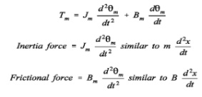
Now shaft torque Tm is used for driving load against the inertia and frictional torque
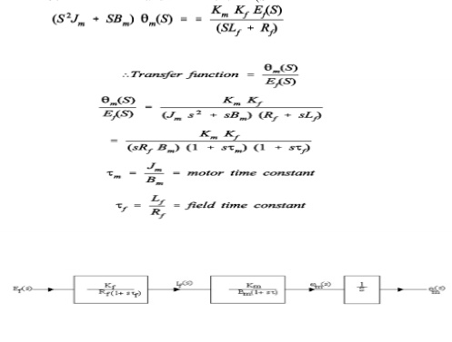
finding Laplace Transforms of equations Tm (s) = Km Kf If(s)
Ef (s) = (SLf + Rf) If (s)
Tm (s) = Jms 2m (s) + Bms2m (s)
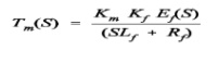
Eliminate If (s) from equations (4) and (5)Input = Ef(S)
Output = Rotational displacement 2m (S
ii.Armature Controlled D.C. Servo Motor
Assumptions:
(i)Flux is directly proportional to current through field winding. Nm = Kf If = constant
(ii) Torque produced is proportional to product of flux and armature current.
T = K`m N Ia
T = K`mKf If Ia
(iii)Back e.m.f is directly proportional to shaft velocity Tm, as flux N is constant