
ASSEMBLY OF PARTS
PRE-REQUISITE DISCUSSION
Assembly modeling is a technology and method used by computer-aided design and product visualization computer software systems to handle multiple files that represent components within a product. The components within an assembly are represented as solid or surface models.
ASSEMBLY MODELING OF PARTS
• Assembly modeling is a combination of two or more components using parametric relationships.
• Typically a designer would start with a base part
• Add other components to the base part using merge commands.
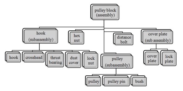
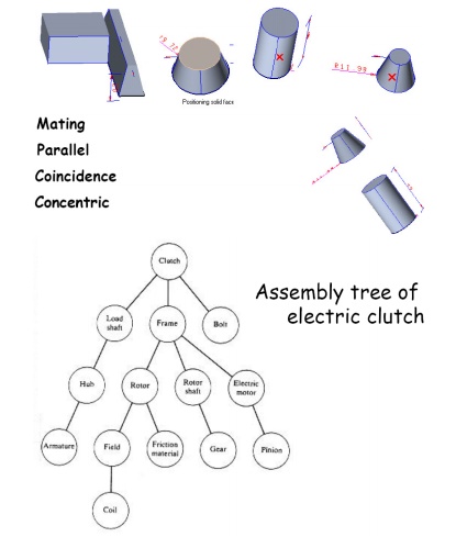
Assembly Tree
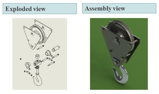
Exploded view
An exploded view consists of series of steps. One can create steps by selecting and dragging parts in graphical area.
Example - Assembly of Pulley block
Bottom-up assembly approach - :
• Allows the designer to use part drawings that already exist (off the shelf)
• Provides the designer w ith more control over individual parts
• Multiple copies (instan ces) of parts can be inserted into the assembly
Top-down assembly approach - :
• The approach is ideal for large assemblies consisting of thousands of parts.
• The approach is used to deal with large designs including multiple design teams.
• It lends itself well to t he conceptual design phase
• E.g. :
▫ Piping and fittings
▫ Welds
▫ Lock pins
Degrees of freedom -:
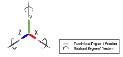
Translation – movement along X, Y, and Z axis
• Rotation – rotate about X, Y, and Z axis
Mating conditions -:
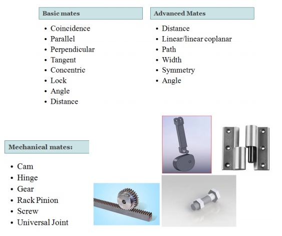
Assembly Constraints
• Constraints can be used to create permanent relationships between parts
• THEY use the same commands as 2D constraints
• Typical constraints:
– two faces meet
– axes coincident
– two faces parallel at fixed distance
Assembly sequence affects
• difficulty of assembly steps
• need for fixture
• potential for parts damage during assembly and part mating
• ability to do in-process testing
• occurrence of the need for reworking
• time of assembly
• assembly skill level
• unit cost of assembly
Mating condition
• Part coordinates MCS (modeling coord.)
• Base part: Datum
• Global CS
• Local CS
• Explicit position and direction vs mating conditions
• 4 x 4 homogeneous transformation matrix
Mating feature
Types: against, fits, contact, coplanar fits: center lines are concentric
• Mating condition = mating type + two faces
• Normal vector + one point on the face
• against: two normal vectors are in against directions
• fits: between two cylinders: center lines are concentric
• Against and fits allows rotation and translation between parts
Interference fit
• Fits is clearance fit
• tight fits is interference fit
• Coplanar: two normal vectors are parallel
• ‘Coplanar’ complements ‘against’
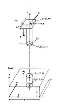
Example Pin and block
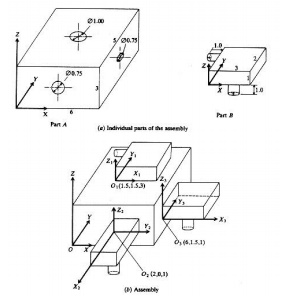
Assembly from instances
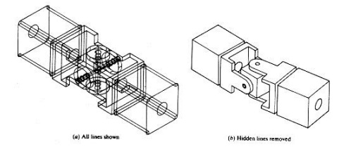
Exploded view of universal joint
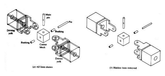
Assembly view of universal joint
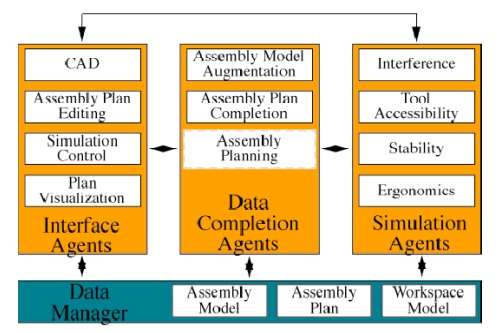
LAYOUT OF INTELLIGENT ASSEMBLY MODELING AND SIMULATION
The goal of IAMS is to avoid this expensive and time-consuming process by facilitating semblability checking in a virtual, simulated environment.
In addition to part-part interference checking, the IAMS tool will check for tool accessibility, stability, and ergonomics.
Intelligent Assembly Modeling and Simulation
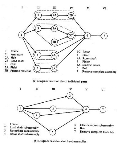
PRECEDENCE DIAGRAM
• Designed to show all the possible assembly sequences of a product.
• Each individual assembly operation is assigned a number.
• Diagram is usually organized into columns
PRODUCTION DRAWING LIMITS, FITS AND TOLERANCE
Limit system
There are three terms used in the limit system:
1. Tolerance: Deviation from a basic value is defined as Tolerance. It can be obtained by taking the difference between the maximum and minimum permissible limits.
2. Limits: Two extreme permissible sizes between which the actual size is contained are defined as limits.
3. Deviation: The algebraic difference between a size and its corresponding basic size. There are two types of deviations: 1) Upper deviation 2) Lower deviation
The fundamental deviation is eith er the upper or lower deviation, depending on which is closer to the basic size.
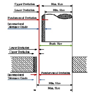
Tolerances
Due to human erro rs, machine settings, etc., it is nearly impossib le to manufacture an absolute dimension as specified by the designer. Deviation in dimensi ons from the basic value always arises. Thi s deviation of dimensions from the basic v alue is known as Tolerance.
The figure shows mechanical tolerances which occur during operations.
Fits
The relation between two mating parts is called fit. Depending upon the actual lim its of the hole or shaft sizes, fits may be classified as clearance fit, transition fit and interference fit.
Clearance fit
Clearance fit is defined as a cleara nce between mating parts. In clearance fit, ther e is always a positive clearance between the hole and shaft.
Transition fit
Transition fit may result in either an interference or clearance, depending upon th e actual values of the tolerance of individual parts.
Interference fit
Interference fit is obtained if the difference between the hole and shaft sizes is negative before assembly. Interference fit generally ranges from mini mum to maximum interference. The two extr eme cases of interference are as follows:
Minimum interference
The magnitude of the difference (negative) between the maximum size of the hole and the minimum size of the shaft in an interference fit before assembly.
Maximum interference
The magnitude of the difference between the minimum size of the hole and the maximum size of the shaft in an interference or a transition fit before assembly.
Hole Basis and shaft basis system:
In identifying limit dimensions for the three classes of fit, two systems are in use:
1. Hole basis system: The size of the shaft is obtained by subtracting the allowance from the basic size of the hole. Tolerances are then applied to each part separately. In this system, the lower deviation of the hole is zero. The letter symbol indication for this is 'H'.
2. Shaft basis system: The upper deviation of the shaft is zero, and the size of the hole is obtained by adding the allowance to the basic size of the shaft. The letter symbol indication is 'h'.