
1 Dielectrics
1.1 Properties
2 Fundamental definitions and Properties of electric dipole
3 Various polarization mechanisms involved in dielectric
3.1 Electronic polarization
3.2 Ionic polarization
3.3 Orientation polarization
3.4 Space charge polarization
3.5 Total polarization
4 Active and Passive Dielectrics
5 Frequency and Temperature on Polarization of Dielectrics
5.1 Frequency Dependence
5.2 Temperature Dependence
6 Internal field or Local field
6.1 Definition
6.2 Derivation
6.3 Clausius – Mosoti Equation
7 Dielectrics and Loss Tangent
7.1 Loss in purified gas
7.2 Loss in commercial dielectric
7.3 Power loss
8 Dielectric Breakdown
8.1 Types of dielectric breakdown
8.2 Remedies for breakdown mechanisms
9 General Applications
10 Applications of dielectric materials
10.1 Dielectrics in capacitors
10.2 Insulating materials in transformers
11 Ferro-electrics
11.1 Properties
11.2 Applications
1 DIELECTRICS
Solids which have an energy gap of three eV or more are termed as insulators. In these materials, it is almost not possible to excite the electrons from the valence band to conduction band by an applied field. Generally dielectrics are also called as insulators, thereby poor conductors of electricity. However they allow movement of some electrons at abnormally high temperatures, causing a small flow of current.
Dielectrics are non-metallic materials of high specific resistance ρ, negative temperature coefficient of resistance (-α), largeandinsulation resistance. Insulation resistance will be affected by moisture, temperature, applied electric field and age of dielectrics.
Dielectric materials are electrically non-conducting materials such as glass, ebonite, mica, rubber, wood and paper. All dielectric materials are insulating materials. The difference between a dielectric and an insulator lies in their applications.
If the main function of non-conducting material is to provide electrical insulation, then they are called as insulator. On the other hand, if the main function of non-conducting material is to store electrical charges then they are called as dielectrics.
1.1 PROPERTIES
Generally, the dielectrics are non-metallic materials of high resistivity.
The have a very large energy gap (more than 3eV).
All the electrons in the dielectrics are tightly bound to their parent nucleus.
As there are no free electrons to carry the current, the electrical conductivity of dielectrics is very low.
They have negative temperature coefficient of resistance and high insulation resistance.
2 FUNDAMENTAL DEFINITIONS AND PROPERTIES ELECTRIC DIPOLE
A system consisting of two equal and opposite charges n(+q, -q) separated by a distance (d) is called an electric dipole.
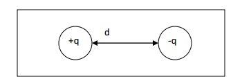
DIPOLE MOMENT (Μ)
The product of the magnitude of the charge (q) and distance between two charges (d) is called as dipole moment.
Dipole moment = qd (coulomb-metre)
PERMITTIVITY (Ε)
The permittivity represents the dielectric property of a medium. It indicates easily polarisable nature of material. Its unit is farad/metre
DIELECTRIC CONSTANT (Ε R)
A dielectric characteristic of a material is determined by its dielectric constant. It is a measure of polarisation of the dielectrics.
Definition
It is the ratio between absolute permittivity of the medium (ε) and permittivity of free space (εo).
Dielectric constant = Absolute permittivity (ε) / Permittivity of free space (ε o)
εr= εo / ε
POLARIZATION
Definition
The process of producing electric dipoles inside the dielectric by the application of an external electrical field is called polarization in dielectrics.
POLARISABILITY (Α)
It is found that the average dipole moment field (E).
It is found that the average dipole moment field (E).
μ α E
or μ = α E
Where (α) is the polarisability.
α = μ / E
Polarisability is defined as the ratio of average dipole moment to the electrical field applied. Its unit is farad m2.
Polarisation vector [Vactor P]
It is defined as the average dipole moment per unit volume of a dielectric. If N is the number atoms per unit volume of a dielectric and (μ) is average dipole moment per atom, then

3 VARIOUS POLARIZATION MECHANISMS INVOLVES IN DIELECTIC
Dielectric polarization is the displacement of charged particles under the action of the external electric field. There are number of devices based on this concept. Those devices are rectifiers, resonators, amplifiers and transducers, which converts electrical energy in to other forms of energy.
Dielectric polarization occurs due to several microscopic mechanisms.
Electronic polarization
Ionic polarization
Orientational polarization
Space-charge polarization
3.1 ELECTRONIC POLARIZATION
Electronic polarization occurs due to displacement of positively charged nucleus and negatively charged electrons of an atom in the opposite directions on the application of an electric field. This will result in the creation of dipole moment in the dielectric.
Dipole moment (μ) is proportional to the electric field strength (E).
μ α E
μ = α e E
Where (α e) is proportionality constant and it is known as electronic polarizability.
Electronic polarization takes place in almost all dielectrics.
Calculation of electronic polarizability
WITHOUT ELECTRIC FIELD
Consider an atom of a dielectric material of nuclear charge Ze, where Z is the atomic number. The electrons of charge (-Ze) are distributed uniformly throughout the atom (sphere) of radius R as shown in fig.
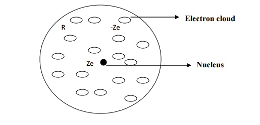
The centres of the electron cloud and the positive nucleus are at the same point and hence there is no dipole moment.
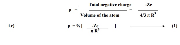
Negative charge density of an atom of radius R is given by
WITH ELECTRIC FIELD
When the atom of the dielectric is placed in an electric field of strength E, two phenomenons occur.
Lorentz force (due to electric field) will tend to move the nucleus and electron cloud of that atom from their equilibrium positions. The positive nucleus will move towards the field direction and the electron cloud will move in the opposite direction of the field as shown in fig.
After separation, an attractive coulomb force arises between the nucleus and the electron cloud which will tend to maintain the original equilibrium position.
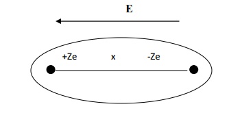
The electron cloud and the nucleus move in opposite directions and they are separated by a distance x, where there is a formation of electric dipole in the atom.
When these two forces equal and opposite, there will be a new equilibrium between the nucleus and the electron cloud of the atom.
Lorentz force between the nucleus and the electron FL = charge x electrical field
= ZeE ---------(2)
Coulomb attractive force between the nucleus and the electron cloud being separated at a distance x,

Total number of negative charges enclosed
In the sphere of radius x = charge density x volume of the sphere of Radius x
Total positive charge of an atom present in the sphere of radius x,
Qp = + Ze
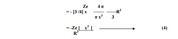
Substituting equation 4 in 3 we have
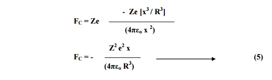
At equilibrium, Coulomb force and Lorentz must be equal and opposite.
FL = - FC
Substituting for FL and FC from equation 2 and 5 we have
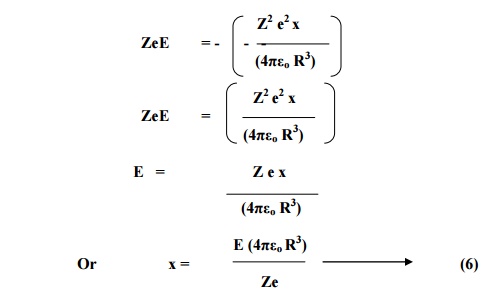
From the definition of dipole moment, induced dipole moment (μ ind) is given by
μind = magnitude of charge x displacement
μind = Ze x
and dipole moment in terms of polarizability,
μind = αe E -----(7)
Substituting the value of x from 6 in 7 we have
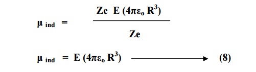
On comparing equation 8 and 9, we have
μind = α e E
Where αe = 4πεo R3 is called electronic polarizability.
Electronic polarization is independent of temperature.
It is proportional to the volume of atoms in the material.
Electronic polarization takes place in all dielectrics.
3.2IONIC POLARIZATION
Ionic polarization is due to the displacement of catios (+ ve ions) and anions (- ve ions) in opposite directions. (e.g. NaCl crystal) by the influence of external field.
When an electric field (E) is applied on an ionic dielectric, there is shift of one ion with
respect to another from their mean position. The positive ion displace in the direction of applied
electric field through the distance x 1. The negative ions displace in opposite direction trough the distance x2 as shown in the fig.
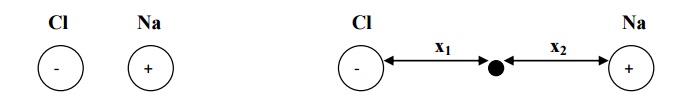
We assume that there is one cation and one anion in each unit cell of that ionic crystal.
Hence, the net distance between two ions
x = x1 + x2 -------(1)
When the ions are displaced from their mean position in their respective directions the restoring forces appear which tend to ions back to their mean position. The restoring force produced is proportional to the displacement.
For positive ion
Restoring1 force F α x
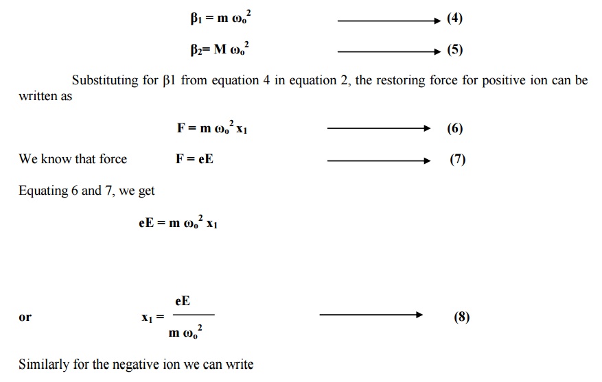
Or restoring force acting on positive ion F = β1x1 ---------(2)
For negative ion
Restoring force F α x2

Where β1 and β2 are restoring force constants which depend up on the masses of ions and angular frequency of the molecule in which ions are present.
If m is the mass of positive ion, M is the mass of negative ion and ωo is the angular
frequency, then
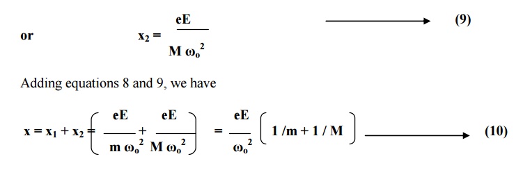
The dipole moment is equal to the product of charge and distance of separation between the charges.
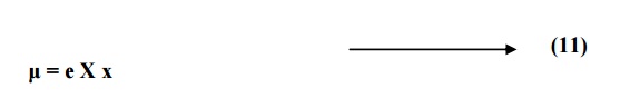
Substituting for x from equation 10 in equation 11, we have
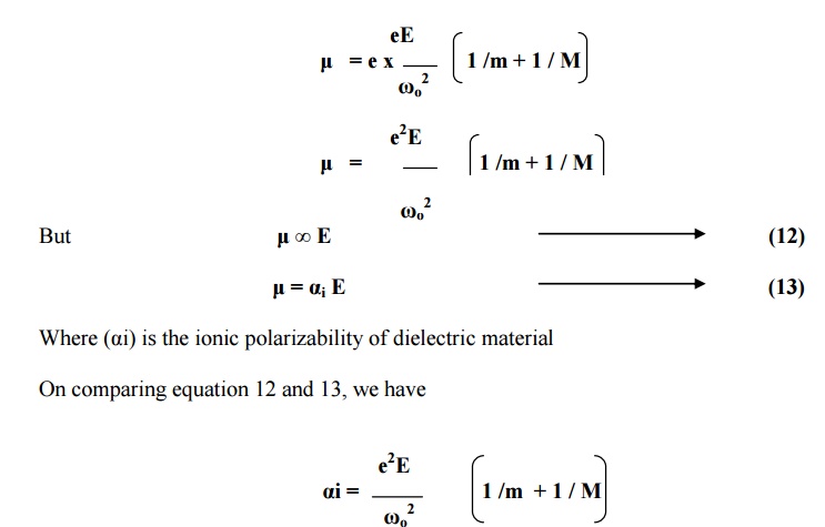
Conclusion
Ionic polarizability () is inversely proportional to the square of angular frequency of the ionic molecule.
It is directly proportional to its reduced mass given by
It is independent of temperature.
3.3 OREINTAIONAL POLARIZATION
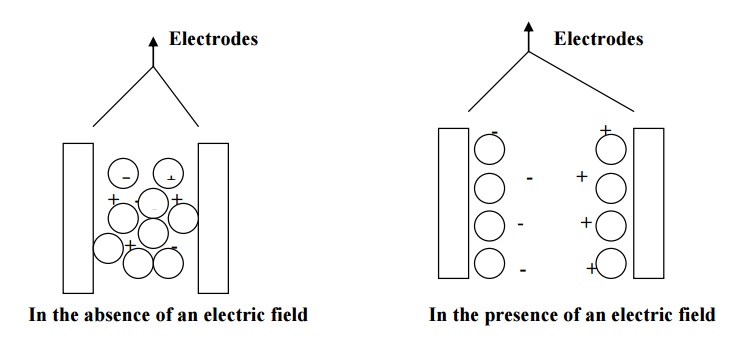
Orientational polarization takes place only in polar dielectrics. Polar dielectrics have molecules with permanent dipole moments even in the absence of external electric field.
When the polar dielectrics are subjected to external electric field, the molecular dipoles are oriented in the direction of electric field.
The contribution to polarization due to orientation of molecular diploes is called orientational polarization.
Orientational polarization depends upon temperature when the temperature is increased , thermal energy tends to disturb the alignment.
From the Langevin’s theory of paramagnetism , net intensity of magnetization
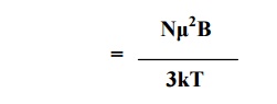
Since the same principle can be applied to the application of electric field in dielectrics, we may write
Orientational polarization, Po =
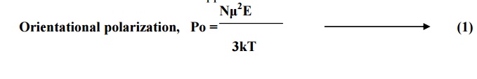
But, orientational polarization is proportional to applied field (E) and it is given by
Po =o E Nα ----(2)
Comparing equations 1 and 2, we get
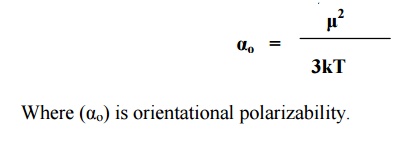
Conclusion
The orientation polarizability is inversely proportional to absolute temperature of the material.
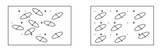
3.4 SPACE CHARGE POLARIZATION
Space-charge polarization occurs due to accumulation of charges at the electrodes or at the interfaces of multiphase dielectric material.
When such materials subjected to an electrical field at high temperature, the charges get accumulated as shown in fig. these charges create diploes.
As a result, polarization is produced. This kind of polarization is known as space-charge polarization. Space-charge polarization is very small when compared to other polarization mechanisms and it is not common in most of the dielectrics.
e.g- ferrites and semiconductors.
3.5 TOTAL POLARIZATION
α=e +αi+αo
Since the space- charge polarization is very small and it is negligible.
Substituting the corresponding expressions, we have
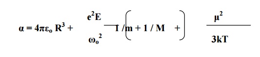
We know that the total polarization P = N E α
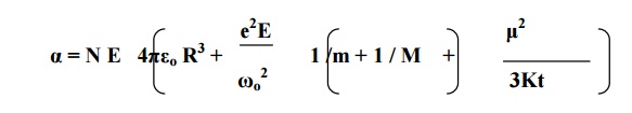
This equation is known as Langevin –Debye equation
4 ACTIVE AND PASSIVE DIELECTRICS
The dielectric materials may be classified as solid, liquid and gas dielectrics.
In solid form they may be polymeric such as nylon, pvc, rubber, Bakelite, asbestos and wool or
may belong to the ceramic family such as glass, silica, mica, porcelain, etc.
In liquid form they may be mineral insulating oils, synthetic insulating oils, tec.
In gaseous form they may be air, nitrogen, sulphur hexafluoride, inert gases etc.
The dielectrics can also be classified as active and passive dielectrics based on their applications.
Active Dielectrics
When dielectric is subjected to external electric field, if the dielectric actively accept the electricity, then they are termed as active dielectrics. Thus active dielectrics are the dielectrics which can easily adapt itself to store the electrical energy in it.
Examples: Piezo-electrics, Ferro-electric etc.,
Passive Dielectrics
These dielectrics are also called insulating materials. As the name itself suggest that it will act as an insulator, conduction will not take place through this dielectrics. Thus passive dielectrics are the dielectrics which restricts the flow of electrical energy in it.
Examples: All insulating materials such as glass, mica, etc.,
5 FREQUENCY AND TEMPERATURE ON POLARISAION OF DIELECTRICS
When an alternating electric field is applied across the material, polarization occurs as a function of time.
Polarization as a function of time t is given by
P (t) = P [1 –e(-t/tr)]
Where P is maximum polarization that occurs due to the static field applied for a long time. tr is relaxation time.
5.1 FREQUENCY DEPENDENCE
Electronic polarization is the fastest polarization which will complete at the instant the field is applied. The reason is that the electrons are lighter elementary particles than ions.
Therefore even for very high frequency applied (in the optical range) electronic polarization occurs during every cycle of the applied field.
Ionic polarization is little slower than electronic polarization. Because ions are heavier than the electron cloud, the time taken for displacement is large. In addition the frequency of applied field with which the ions will be displaced is equal to the frequency of lattice vibration (10 13 Hz).
If the frequency of the applied field is less than 10 13 Hz, the ions have enough time to respond during each cycle of the applied field.
Orientational polarization is even slower than ionic polarization. This type of polarization occurs only at electrical frequency range (= 106Hz).
Space-charge polarization is the slowest because have to diffuse over several atomic distance. This process occurs at very low frequencies (102 Hz) as shown in fig.
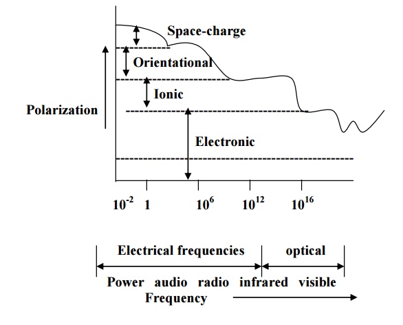
Figure explains the four types of polarization at different frequency ranges. At optical frequencies (-1015Hz), electronic polarization alone present. At -1013 Hz range, ionic polarization occurs in addition to electronic polarization.
At 106 to 1010 Hz range, contribution due to orientation polarization gets added while at 102 Hz range, space-charge polarization also contributes.
It is noted that at low frequencies, all the four types of polarizations occur and total polarization is very high.
Total polarization decreases with increase in frequency and becomes minimum at optical frequency range.
5.2TEMPERATURE DEPENDENCE
When a dielectric material is subjected to ordinary conditions of increasing temperature, electronic distribution in n the constituent molecules are not affected.
Hence there will be no temperature influence on electronic and ionic polarization mechanisms. Therefore electronic and ionic polarizations are practically independent of temperature.
An increase in temperature brings a high degree of randomness in molecular orientation of the material. This will affect the tendency of permanent dipoles to align along direction of the field. Hence, orientation polarization decreases with increase in temperature.
However in space-charge polarization, increase in temperature helps the ion movement by diffusion. As a result it will increase the polarization.
Thus both the orientational and space-charge polarization mechanisms are strongly temperature dependent.
6 INTERNAL FIELD OR LOCAL FIELD
6.1 DEFINITION
When a dielectric material is placed in an external electric field, it produces an induced dipole moment.
Now, two fields are acting at any point inside dielectrics are
Macroscopic electrical field due to external electric field.
Electrical field due to electric dipole moment.
These long range coulomb fields produced due to dipoles is known as internal field or local field. This internal field is responsible for polarization of each atom or molecule in the solid.
6.2 DERIVATION
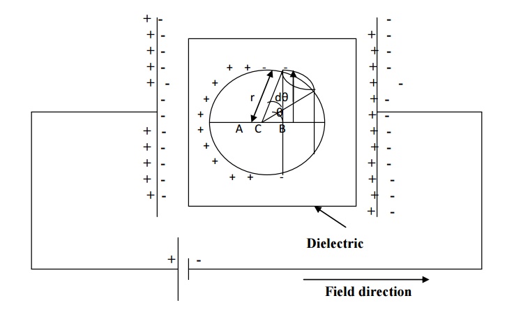
LORENTZ METHOD TO FIND INTERNAL FIELD
The dielectric material is uniformly polarized by placing it in between two plates of parallel plate capacitor as shown in figure.
Assume an imaginary spherical cavity around an atom for which the internal field must be calculated at its centre.
The internal field (E int) at the atom site is considered to be made up of the following four components. E1, E2, E3 and E4.
E int = E1+ E2+ E3+E4
Where E1 –Electrical field due to charges on the plates of the capacitor
E2 –Electric field due to polarized charges (induced charges) on the plane surface of the dielectric.
E3 –Electric field due to polarized charges induced on the surface of the imaginary spherical cavity.
E4 –Electric field due to permanent dipoles of atoms inside the spherical cavity considered.
Macroscopically we can take E = E1 + E2. i.e., the electrical field externally applied (E1) and the electrical field induced on the plane surface of the dielectric (E2) can be considered as a single electrical field.
If we consider a dielectric that is highly symmetric, the electrical field due to dipoles present inside the imaginary cavity will cancel out of each other. Therefore the electrical field due to permanent dipoles E4 = 0
Now, the equation (1) is rewritten as
E int = E +E3
Calculation of E3
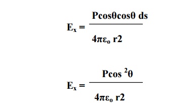
Let us consider small area ds on the surface of the spherical cavity. It is confined within an angle dθ at the angle θ in an direction of electric field
Polarization P is parallel to E. PN is the component of polarization perpendicular to the area ds as shown in the figure.
PN = Pcosθ
q’ is the area chargeds. Polarizationonisal so the defined as the surface charges per unit area. q' / ds
PN = Pcosθ = (q' / ds)
Electric field intensity at C due to charge q’ (Coulomb force) is given by
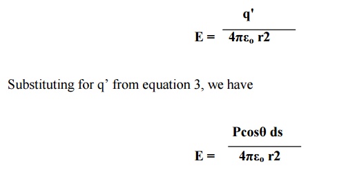
This electrical field intensity is along the radius r and it can be resolved in to two components (Ex and Ey) as shown in figure.
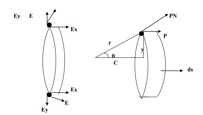
The component of intensity parallel to the electrical field direction,
Ex = E cosθ
Substituting for E from equation 4 in 5, we have
The component of intensity perpendicular to the field direction,
Ex = E sinθ
Since the perpendicular components are in opposite directions, they cancel out each other. Hence, the parallel components alone are taken onto consideration.
Now, consider a ring area dA which is obtained by revolving ds about AB as shown in fig(b)
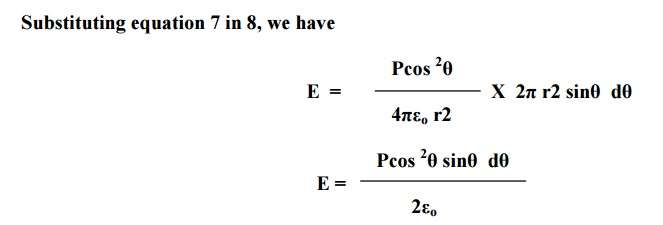

Electric field intensity due to charges present in the whole sphere is obtained by integrating equation 9 within the limits 0 to π. This electrical field is taken as E3.
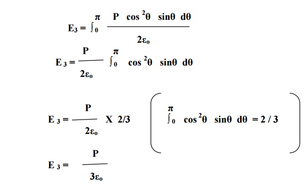
Substituting equation 10 in equation 2, we get
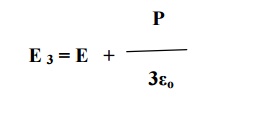
E int is the internal field or Lorentz field.
6.3 CLAUSIUS – MOSOTI EQUATION
Let N be the number of molecules per unit volume and α be the molecular polarizability.
Then
Total polarization, P = N α Eint
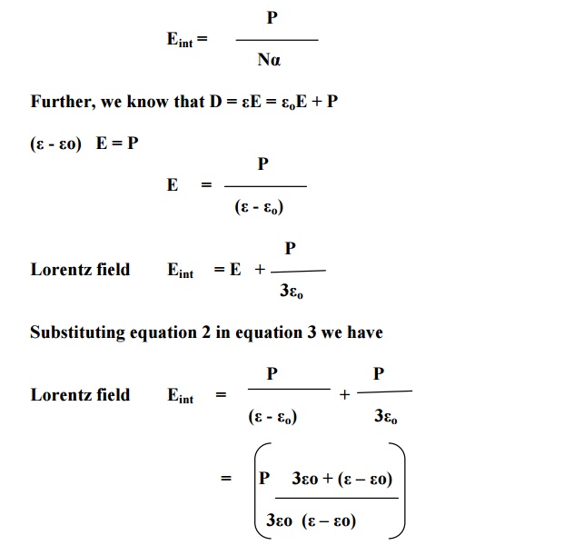
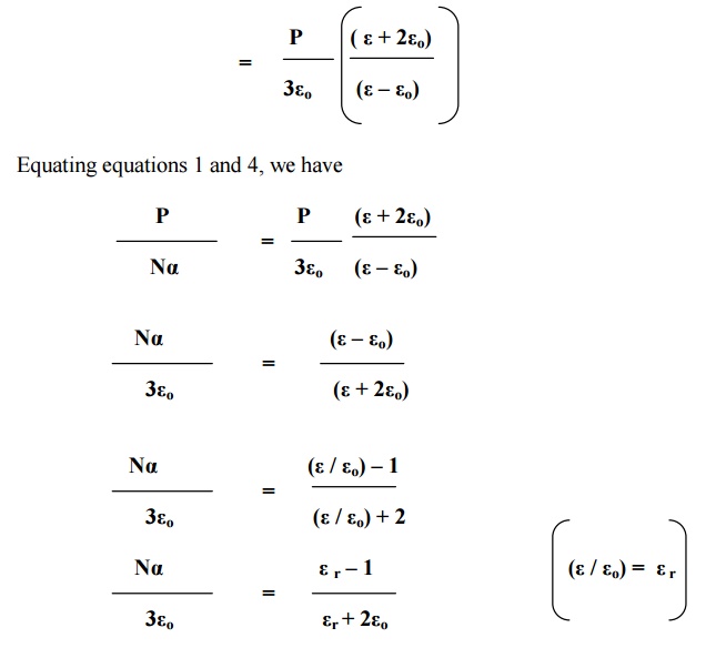
Where εr is dielectric constant.
Equation 5 is Clausius- Mosotti relation which relates the dielectric constant (a macroscopic quantity) of the material with polarizability (a microscopic quantity).
7 DIELECTRICS AND LOSS TANGENT
If a dielectric is subjected to an electric field, the electrical energy is absorbed by the dielectric and certain quantity of electrical energy is dissipated in the form of heat energy. This is known as dielectric loss.
The dielectric loss can occur both in direct and alternating voltages. The dielectric loss is less in direct voltage than that of the alternating voltage.
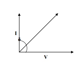
7.1LOSS IN PURIFIED GAS
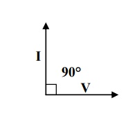
If an alternating voltage is applied across the capacitor having vacuum or purified gas then the resulting current leads the applied voltage by 90°, as shown in figure. If I lead V exactly by 90° we can say that no electrical energy is lost.
Explanation
We know the power loss PL = VI cosθ
When θ=90°;L P
7.2LOSS IN COMMERCIAL DIELECTRIC
Now, when a practical dielectric is present in the current leads the voltage by (90-δ), the shows that there is some loss in electric energy and δ is called loss angle, as shown in fig.
Explanation
In this case the power loss PL = VIcosθ
Since- δθ=90; we L = VIcos have(90- δ)P
PL = VI sin δ ------(1)
We know V = IR
I = V / R
If the capacitive resistance is Xc then we can write,
I = V / Xc (2)
Substituting equation 2 in 1, we get
7.3 POWER LOSS
Here tan δ is called the power factor of the dielectric. If f, C, V are constants then
PL ∞ tan δ
Naturally the power loss varies with frequency. The power loss at various frequency ranges is shown in fig.
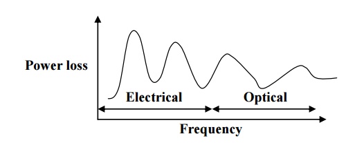
In the electrical frequency regions the power is high, due to the diffusion of ions from one equilibrium position to another.
In the optical region the power loss is less because here the dielectric loss is associated with electrons
8 DIELECTRIC BREAKDOWN
When a dielectric is placed in an electric field and if the electric field is increased, when the field exceeds the critical field, the dielectric loses its insulating property and becomes conducting. i.e., large amount of current flows through it. This phenomenon is called dielectric breakdown.
The electric field strength at which the dielectric breakdown occurs is known as dielectric
The dielectric strength = strength. Dielectric voltage / Thickness of dielectric
8.1TYPES OF DIELECTRIC BREAKDOWN
Intrinsic or avalanche breakdown
Thermal breakdown
Chemical and electrochemical breakdown
Discharge breakdown
Defect breakdown
INTRINSIC BREAKDOWN
When dielectric is subjected to electric field then the electrons in the valance band acquire sufficient energy and go to conduction band by crossing the energy gap and hence become conduction electrons. Therefore large current flows and it is called intrinsic breakdown or zener breakdown.
AVALANCHE BREAKDOWN
These conduction electrons on further application of field then collide with the valance electrons in the co-valent band and remove more electrons hence transferring them as conduction electrons.
These secondary conduction electrons again dislodge some other bound electrons in the valance band and this process continues as a chain reaction. Therefore very large current flows through the dielectrics and hence called as avalanche breakdown.
Characteristics
It can occur at lower temperatures.
It requires relatively large electric fields.
This kind of breakdown occurs in thin samples.
It occurs within short span of time
THERMAL BREAKDOWN
In general, when a dielectric is subjected to an electric field, heat is generated. This generated heat is dissipated by the dielectric. In some cases the heat generated will be very high compared to the heat dissipated. Under this condition the temperature inside the dielectric increases and heat may produce breakdown. This type of breakdown known as thermal breakdown.
Characteristics
It occurs at higher temperatures.
It requires moderate electric fields.
It depends on the size and shape of the dielectric material.
It occurs in the order of milliseconds.
CHEMICAL AND ELECTROCHEMICAL BREAKDOWN
This type of breakdown is almost similar to the thermal breakdown. If the temperature is increased mobility of ions will increase and hence the electrochemical reaction may be induced to take place.
Therefore when mobility of ions increased, insulation decreases and hence dielectrics becomes conducting. This type of breakdown is called as chemical and electrochemical breakdown.
Characteristics
It occurs only at low temperatures.
It depends on concentration of ions, magnitude of leakage current.
It occurs even in the absence of electric field.
DISCHARGE BREAKDOWN
Discharge breakdown occurs when a dielectric contains occluded air bubbles as shown in fig. when this type of dielectric subjected to electrical field, the gases present inside the material will easily ionize and thus produce large ionization current. This is known as discharge breakdown.
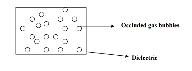
Characteristics
It occurs at low voltages.
It occurs due to the presence of occluded air bubbles.
It depends upon the frequency of the applied voltage.
DEFECT BREAKDOWN
Some dielectric have defects such as cracks, pores, blow holes etc. these vacant position may have moisture which leads to breakdown called as defect breakdown.
8.2 REMEDIES FOR BREAKDOWN MECHANISMS
To avoid breakdown, the dielectric material should have the following properties.
It should have high resistivity.
It must possess high dielectric strength.
It should have sufficient mechanical strength.
Dielectric loss should be low.
Thermal expansion should small.
It should be fire proof.
It should resistive to oils, liquids and gases.
It must have less density.
There should not be any defects.
It must be in pure form.
9 GENERAL APPLICATIONS
The following are the some of the applications of the dielectric materials:
2. Quartz crystal is used for the preparation of ultrasonic transducers, crystal oscillators, delay lines, filters etc.
3. Barium Titanate is used for the preparation of accelerometers.
4. Lead Zirconate Titanate (PbZrx Ti1-x O3) is used for the preparation of earphones, microphones, spark generators (gas lighter, car ignition), displacement transducer, accelerometers etc.
5. Mica is used in electrical machines, switch gears, armature winding, hot plates etc.
6. Dielectric materials are used as an insulating material in power cables, signal cables, electric motors, circuit breakers etc.
7. In radiation detectors, thermionic valves and electric devices, the dielectric materials are used.
8. The pyroelectric materials are used as radiation detector.
9. The dielectric materials are used in strain gauges, capacitors and resistors.
10. The electro-optic devices are prepared using dielectric material.
10 APPLICATIONS OF DIELECTRIC MATERIALS
Almost all electrical devices depend on insulating material in some way or other. Insulating materials are used in power and distribution transformers, rotating machines, capacitors, cables, and electronic applications.
10.1 DIELECTRICS IN CAPACITORS
For dielectrics used in capacitors, it should possess the following properties.
It must have high dielectric constant.
It should possess high dielectric strength.
It should have high specific resistance.
It should also have low dielectric loss.
Uses
Thin sheets of papers filled with synthetic oils are used as dielectrics in the capacitors.
Tissue papers and polypropylene films with dielectrol are used in power capacitors.
Mica used as dielectrics in discrete capacitor.
An electrolytic solution of sodium phosphate is used in wet type electrolytic capacitors.
Ceramic materials such as barium titanate and calcium titanate are used in disc capacitors and high frequency capacitors respectively.
10.2 INSULATING MATERIALS IN TRANSFORMERS
For dielectrics to act as insulating materials, it should possess the following properties.
It should have low dielectric resistant.
It should possess low dielectric loss.
It must have high resistance.
It must possess high dielectric strength.
It must have high moisture resistance.
It should have adequate chemical stability.
Uses
Ceramics and polymers are used as insulators.
Paper, rubber, plastics, waxes etc are used to form thin films, sheets, tapes, rods, etc. PVC, is used to manufacture pipes, batteries, cables etc.
Glass, mica, asbestos, alumina are used in ceramics.
Liquid dielectrics such as petroleum oils, silicone oils are widely used in transformers, circuit breakers, etc.
Synthetic oils such as askarels, sovol, etc are used as coolent and insulant in high voltage transformers.
11 FERRO-ELECTRICITY AND APPLICATIONS
Ferro –electricity
When a dielectric material exhibits electric polarization even in the absence of external field, it is known as ferro-electricty and these materials termed as ferro-electric.
11.1 FERRO-ELECTRICS
Ferro-electrics are anisotropic crystals which exhibit spontaneous polarization, i.e. they exhibit polarization even in the absence of external electric field.
Examples
Rochelle salt,
Potassium niobate,
Lithium tentalate,
Ammonium dihydrogen phosphate,
Potassium dihydrogen phosphate,
Barium titanate.
11.2 PROPERTIES
The dielectric constant of these ferro-electric materials is above 2000 and it will not vary with respect temperature.
The dielectric constant(ε) reaches maximum value only at a particular temperature called Curie temperature.
The polarization does not varies linearly with respect to electric field and hence these materials are also called as non-linear dielectrics.
Ferro-electric exhibits electric polarization easily, even in the absence of external electric field. They exhibit domain structure similar to that of a Ferro-electric material.
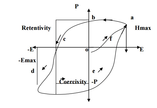
Ferro-electric materials also exhibit hysteresis, similar to that of ferromagnetic materials.
11.3 APPLICATIONS
Ferro-electric materials are used to produce ultasonics
They are used in production of piezo-electric materials and in turn to make micro phones. Ferro-electrics are also used in SONAR, strain gauges, etc.
Ferro-electric semiconductors are used to make positors, which is turn are used to measure and control the temperature.
They are also used as frequency stabilizers and crystal controlled oscillators.
Electrets are a type of ferro-electric materials, used in the production of capacitor microphones, gas filters, etc.
Electrets are also used to bond the fractured bones in the human body. Pyro-electric materials are also used to produce high sensitive infrared detectors.