PRE-REQUISITE DISCUSSION
CURVE REPRESENTATION
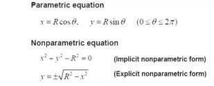
(1) Parametric equation x, y, z coordinates are related by a parametric variable (u or θ)
(2) Nonparametric equation x, y, z coordinates are related by a function
Example: Circle (2-D)
TYPES OF CURVES USED IN GEOMETRIC MODELLING
• Hermite curves
• Bezeir curves
• B-spline curves
• NURBS curves
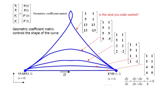
HERMITE CURVES
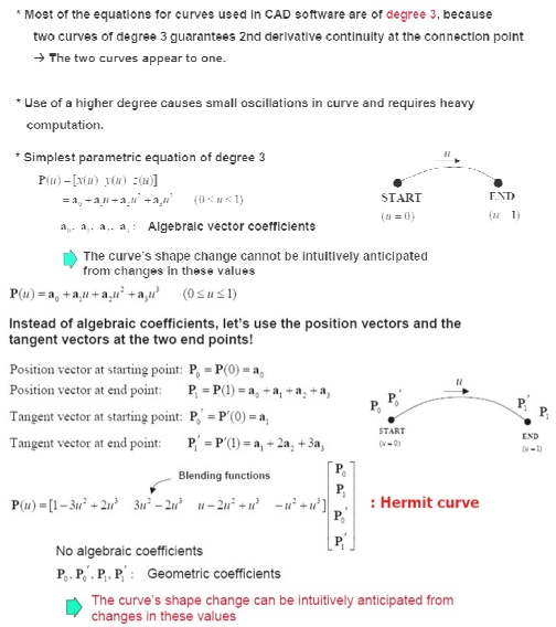
Effect of tangent vector on t he curve’s shape
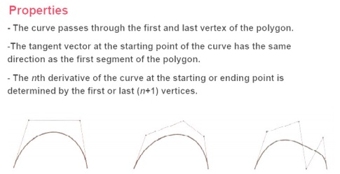
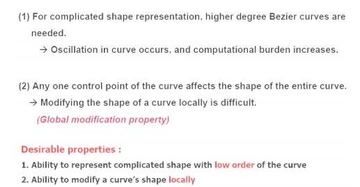
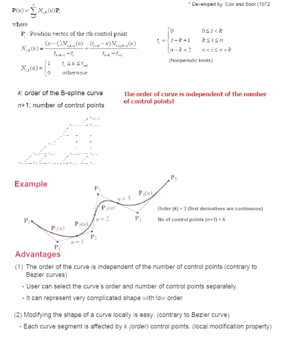
BEZIER CURVE
Two Drawbacks of Bezier Curves
B-SPLINE CURVES
NURBS curve
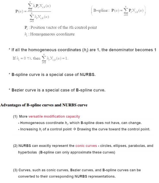
Advantages of B-spline curves and NURBS curve
TECHNIQUES IN SURFACE MODELLING
i. Surface Patch
ii. Coons Patch
iii. Bicubic Patch
iv. Be’zier Surface
v. B-Spline Surface
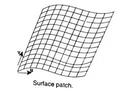
i. Surface Patch
The patch is the fundamental building block for surfaces. The two variables u and v vary across the patch; the patch may be termed biparametric. The parametric variables often lie in the range 0 to 1. Fixing the value of one of the parametric variables results in a curve on the patch in terms of the other variable (Isoperimetric curve). Figure shows a surface with curves at intervals of u and v of 0 : 1.
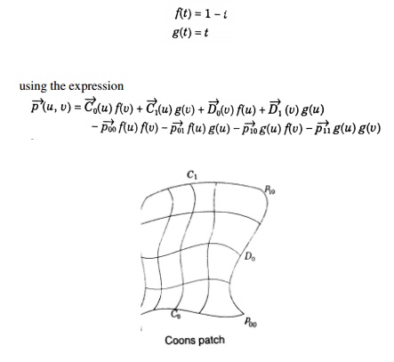
ii. Coons Patch
The sculptured surface often involve interpolation across an intersecting mesh of curves that in effect comprise a rectangular grid of patches, each bounded by four boundary curves. The linearly blended coons patch is the simplest for interpolating between such boundary curves. This patch definition technique blends for four boundary curves Ci(u) and Dj(v) and the corner points pij of the patch with the linear blending functions,
iii. Bicubic Patch
The bi-cubic patch is used for surface descriptions defined in terms of point and tangent vector information. The general form of the expressions for a bi-cubic patch is given by:
This is a vector equation with 16 unknown parameters kij which can be found by Lagrange interpolation through 4 x 4 grid.
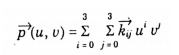
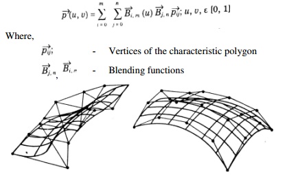
iv. Be’zier Surface
The Be’zier surface formulation use a characteristic polygon
Points the Bezier surface are given by
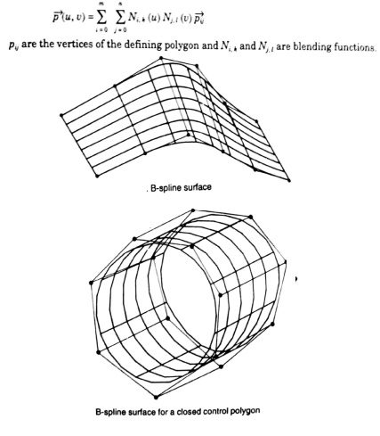
v. B-Spline Surfaces
The B-spline surface approximates a characteristics polygon as shown and passes through the corner points of the polygon, where its edges are tangential to the edges of the polygon
This may not happen when the control polygon is closed
A control point of the surface influences the surface only over a limited portion of the parametric space of variables u and v.
The expression for the B-spline surfaces is given by
GEOMETRIC MODELLING
Geometric modeling is the starting point of the product design and manufacture process. Functions of Geometric Modeling are:
Design Analysis
Evaluation of area, volume, mass and inertia properties
Interference checking in assemblies
Analysis of tolerance build-up in assemblies
Kinematic analysis of mechanisms and robots
Automatic mesh generation for finite element analysis
Drafting
Automatic planar cross-sectioning
Automatic hidden lines and surface removal
Automatic production of shaded images
Automatic dimensioning
Automatic creation of exploded views of assemblies
Manufacturing
Parts classification
Process planning
NC data generation and verification
Robot program generation
Production Engineering
Bill of materials
Material requirement
Manufacturing resource requirement
Scheduling
Inspection and quality control
Program generation for inspection machines
Comparison of produced parts with design
PROPERTIES OF A GEOMETRIC MODELING SYSTEM
The geometric model must stay invariant with regard to its location and orientation The solid must have an interior and must not have isolated parts
The solid must be finite and occupy only a finite shape
The application of a transformation or Boolean operation must produce another solid The solid must have a finite number of surfaces which can be described
The boundary of the solid must not be ambiguous
WIRE FRAME MODELING
It uses networks of interconnected lines (wires) to represent the edges of the physical objects being modeled
Also called ‘Edge-vertex’ or ‘stick-figure’ models Two types of wire frame modeling:
1. 2 ½ - D modeling
2. 3 – D modeling
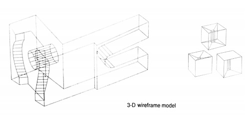
3-D Wire frame models: These are
Simple and easy to create, and they require relatively little computer time and memory; however they do not give a complete description of the part. They contain little information about the surface and volume of the part and cannot distinguish the inside from the outside of part surfaces. They are visually ambiguous as the model can be interpreted in many different ways because in many wire frame models hidden lines cannot be removed. Section property and mass calculations are impossible, since the object has no faces attached to it. It has limited values a basis for manufacture and analysis
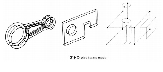
2 ½ - D Wire frame models:
Two classes of shape for which a simple wire-frame representation is often adequate are those shapes defined by projecting a plane profile along its normal or by rotating a planar profile about an axis. Such shapes are not two-dimensional, but neither do they require sophisticated three-dimensional schemes for their representation. Such representation is called 2 ½ - D.