
PROGRAMMING LOGIC CONTROLLERS
DEFINITION OF PLC:
A programmable logic controller (PLC) Program is a specially designed digital operating microprocessor-based controller that uses a programmable memory for internal storage of instructing and for internal storage of instructing and for implementing function such as logic, sequencing, timing, counting and arithmetic in order to control machines and processes.
BASIC COMPONENTS OF PLC:
The PLC hardware system consists of the basic components are
Processor
Memory
Power Supply
Input I Output modules
Programming device
Monitor
Processor:
It is the heart of PLC
He processor processes the signals from input module and generates controlling signals for the system
It also scans and solve the logic of the user program
It consists of ALU, microprocessor unit, memory unit and system power supply
Memory:
The memory unit contains the program stored in it
The programs were written with control actions to be executed by the microprocessor for the input given
RAM is a temporary storage device used to store ladder diagram and for testing and evaluation Then it is stored in ROM where changes cannot done
Power Supply:
The purpose of a power supply unit is to convert the main A.C voltage into a low - level D.C voltage (5V).
The D.C. voltage is supplied to the processor and the circuits in the input and output interface modules. The power supply should be free from heavy loads, noises and voltage fluctuations.
Input / Output Modules:
The Input module receives information from extended devices and sends to processor and communicates the processed information to the external devices through output modules.
The Input devices are mechanical switches, photo sensors, temperature sensors, flow sensors, other type of sensors keypads etc.,
The output devices may include solenoid valves, Relays, contactors, lights, Horns,
Heating elements, fans, Motor starter, signal Amplifiers. Conveyor belt, lift, automatic door etc., I/O devices are also called peripheral devices.
Programming Device:
It is used to enter the required program into the memory of the CPU
The program is developed in programming device and stored into memory unit
BASIC STRUCTURE OR (INTERNAL ARCHITECTURE) OF A PLC SYSTEM:
Central Processing Unit:
The CPU controls and processes all the operations within the PLC.
It is supplied with a clock with a frequency of typically between 1 to 8 MHz.
This frequency determines the operating speed of the PLC and provides the timing and synchronization for all elements in the system.
The information within the PLC is carried by means of digital signals.
The processor is a microprocessor that executes a program to perform the operations specified in a ladder diagram or a set of Boolean equations.
The CPU consists of the following units
Arithmetic and Logic Unit (ALU):
This unit performs data manipulation and arithmetic and logical operations on input I variable data and determines the proper state of the output variables.
The arithmetic operation includes addition, subtraction etc., and logic operations include AND, OR, AND, EXCLUSIVE - OR.
Memory Unit:
Memory termed registers located within the microprocessor and used to store information involved in a program execution.
These programs contain control actions to be executed by the microprocessor for the given input. There are several memory elements in a PLC system.
System Read-only Memory (ROM) gives permanent storage for the operating system and fixed data wed by the CPU.
RAM for the user to develop program and acts a temporary memory.
In addition, temporary buffer stores for the I/O channels.
Control Unit:
A control unit is used to control the timing of operations.
The processor functions under a permanent supervisory operating system that directs the overall operations from data input and output to execution of user programs.
The controller can perform only one operation at a time. So, it scans each of the inputs sequentially, evaluates the ladder diagram program, provide each output(s), and then
repeat the whole process.
Hence, the timing control's necessary for a PLC system.
Memory Unit:
The sequence of instructions to be executed, programs are stored in the memory unit.
During entering and editing including Debugging, the program is stored in the temporary storages called RAM (Random Access memory).
Once the program is completely finished (free & from errors).
It may be 'burned' into ROM
When the ROM is plugged into the PLC, the device is ready to be placed into service in the industrial environment.
For network programmed PLCs, the final PLCs program is downloaded into a special re-programmable ROM (EPROM, PROM, and EEPROM) in the PLC.
Memory may be either volatile type or Non-volatile type.
Volatile Memory:
Volatile memory or temporary memory or Application memory is the user memory, where the user can enter and edit the program.
Volatile memory will lose all its programmed contents if operating power is removed or lost. Therefore, necessary to provide a battery backup power to all times.
Non Volatile Memory:
Non-volatile memory or permanent memory or system memory is (used) a system memory that stores the monitor a booting programs, lookup tables etc.,
This usually programmed and supplied by the manufacturer.
This controls the operation of PLC.
It does not lose its content during power failure.
It does not require any battery.
The ROM memory offers the CPU to use only fixed amount of data.
The Different Types of ROMS are
Mask programmed ROM
PROM
EPROM
EEPROM
Mask Programmed ROM:
It is a special type of ROM which is programmed during manufacturing.
The programmed content stored by this type of ROM memory cannot be altered.
PROM:
PROM stands for programmable Read only memory.
It is a special type of ROM usually programed by manufacturer during manufacturing.
It has the disadvantage of requiring special programming device and once programmed cannot be erased or altered.
EPROM:
EPROM stands for electrically programmable Read only Memory.
Here, the user programs electrically.
One can erase the program completely by shining UV light source or quartz window in package. After the program chip is erased completely, program changes can be made.
When the program developed in RAM, the manufacturers usually load it in EPROM to make permanent storage.
EEPROM:
EEPROM - Electrically Erasable programmable Read-only memory.
Even though, it is a non-volatile memory, it offers some programming flexibility as RAM. One can erase the program completely by electrical signals.
Program changes can be made very easily with the use of a PC with EEPROM software.
It can be electrically programmable by the user.
Buses:
A set of parallel lines that provides communication between various devices of a system is termed as a Bus.
The bus system carries information and data’s to and from the CPU, Memory and I/O units. The information is transmitted in binary form as 0 or 1
Digital signals or electrical signals are flowing inside the bus.
It might be tracks on a printed circuit board (PCB) or wires in a ribbon cable.
The PLC system contains four buses.
They are namely Data Bus, Address Bus, Control bus and system bus.
Data Bus:
The data bus contains 8, 16 or 32 parallel signal lines for sending data between the various devices of a system.
An 8-bit microprocessor has an internal data bus which can handle 8-bit numbers.
The double ended arrows on the bus line show that they are bidirectional.
This means that CPU can read data in from memory or from I/O unit on these lines or it can send data out to memory or to I/O unit on these lines.
Many devices in a system will have their outputs connected to the data bus, but only one device will have its output enabled at a time.
Address Bus:
The Address bus contains 16, 20, 24 or 32 parallel signal lines to carry the Address of the memory locations for accessing stored data.
Every memory location is given a distinct unique address to locate easily and accessed by the CPU either to read or write data.
Control Bus:
The Control bus contains 4 to 10 parallel signal lines to carry the signals used by the CPU that are related to internal Control actions. Typical control bus signals are Memory
read Memory write, I/O Read and I/O write.
I/O System Bus:
The I/O system bus provide the communication between the I/O ports and I/O units
Input / Output Unit:
The I/O units provide the interface between the system and the outside world, allowing for connections to be made through I/O channels to input / output devices.
Programs are entered from a program panel through I/O unit.
INPUT / OUTPUT PROCESSING:
The sourcing and sinking are used to describe the way in which DC devices are connected to PLC
Sourcing:
If a switch is connected to the positive of the battery and current flows from positive to negative, it is said to be the sourcing the current. So, the input device receives current
from the input module.
For the PLC, input unit, hence input module is the source of the current. For the PLC output unit, output module is the source of current as it supplies current to the output
devices. Sourcing output units for interfacing with solenoids.
Sinking:
Here, the input device supplies current to the input module. For the PLC input unit, hence the input module is the sink for the current. Sinking input units are used for
interfacing with electronic equipment.
So, if a switch is connected to the negative of the battery and current flows from positive to negative, by conventional current flow direction, it is said to be the sinking for
Current. For the PLC output unit, the current flows from output device to the output module then the
output module is the sink for current.
STEPS INVOLVED IN INPUT / OUTPUT PROCESSING:
The sequence followed by a PLC when carrying out a program can be as follows:
Scan the inputs associated with one rung of the ladder program
Solve the logic operation involving those inputs.
Set / Reset the outputs for that rung
Move on the next rung and repeat the operations 1, 2, 3
The two methods of Input/ Output processing operations are
Continuous updating
Mass Input / Output copying
Continuous Updating:
The sequence followed thus in continuous updating is as follows:
Fetch and decode the first program instruction
Scan there relevant inputs
Fetch and decode the second program instruction
Scan the relevant inputs etc. For the remaining program instructions
Update outputs
Report the entire sequence.
Mass Input / Output Copying:
The sequence followed in Mass I/O copying is thus:
Scan all the inputs and copy into RAM
Fetch and decode and execute all the program instructions in sequence
Copy all the output instructions to RAM
Update all outputs.
Repeat the sequence
PLC LOGIC:
Instruction Code Mnemonics:
AND Logic Function:
AND logic circuit represents series circuit
AND gate is composed with two inputs and one output.
AND gate produce output when both the inputs are HIGH state.

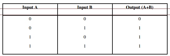
OR Logic Function:
OR logic circuit represents the parallel circuit.
OR Gate is composed of two or more inputs and one output.
OR operation is like addition of binary numbers.
OR gate produce output when any one input are HIGH state.
NOT Logic Function:
NOT function is also known as Inverter.
NOT gate is composed of single input and a single output.
The bubble, or circle, at the output is the standard symbol used to represent inversion.
In NOT gate, there is an output, when there is no input and no output when there is an input
NAND Logic Function:
NAND is a combination of AND and NOT gates.
Arrangement shows AND gate is followed by NOT gate. Hence it is called NOT AND gate. Both the inputs A and B have to be at LOW state to get the output at HIGH state.
NAND Gate is composed of two or more input with a single output. Any one input is in LOW state also output will be HIGH state
NOR Logic Function:
NOR is a combination of OR and NOT gates.
Arrangement shows OR gate is followed by NOT gate. Hence it is called NOT OR gate. Both the inputs A and B have to be at LOW state to get the output at HIGH state.
NOR Gate is composed of two or more input with a single output. Any one input is in HIGH state also output will be LOW state
Exclusive OR (XOR) Logic Function:
When both the inputs are at LOW state the output will be at LOW state
When both the inputs are at HIGH state the output will be at LOW state
When any one input is HIGH state the output will be at HIGH state
latching:
It is necessary to hold an output coil energized, even when the input ceases The term latch is used for the circuit used to carry out such an operation.
Latch circuit is a self – maintaining circuit that maintains its output in an energized state until the next input is updated
TIMER:
A timer is a special counter ladder function that allows the PLC to perform timing operations based on a precise internal clock.
Types of Timers:
Delay ON Timers or ON delay timers
Delay OFF Timers or OFF delay timers
Pulse Timers
Cascaded Timers
ON-OFF Cycle Timers
One Shot Timers
Delay ON Timers:
The term delay is used to indicate that this timer burns on, after waiting for a fixed time delay period.
When there is an input, the timer is energised and starts timing, after some pre-set value, the timer contacts are closed to output.
TON is used to denote ON-delay.
Delay OFF Timers:
OFF delay timers are maintained as ON for a fixed time of delay period before turning off. TOF is used to denote OFF-delay.
Pulse Timers:
Pulse timer switches is another type of Timer which comes either ON or OFF for a fixed period of time as a function of pulses.
TP is used to denote Pulse Timers
Cascaded Timers:
Cascading means more elements are linked together to form a system.
The cascading timers are linked together to give longer delay times which is easily achieved than just one timer.
ON – OFF Cycle Timer:
Timers producing an output for some period and no output for some period and an output for some period.
The timer is designed to switch an output for T sec and off for another T second
One Shot Timers:
One shot timers produces an output for a fixed length of some initiation input.
INTERNAL RELAY:
An internal relay behaves like relays with their associated contacts, buy they are not actual relays whose simulations are controlled by the PLC software.
Internal relays can be very useful in the implementation of switching sequences.
They are often used when there are programs with multiple input conditions.
They are also known as Auxiliary relays or markers.
In using an internal relays, it has to be activated on one rung of a program and then its output used to operate switching contacts on another rung of a program.
COUNTERS:
Counters are used to count a specified number of contact operations.
Types of Counters:
Up Counters
Down Counters
Up Counters:
Up counters count up from the zero to pre – set value
The events are added until the pre – set value is reached
When the counter reaches the set value, its contacts change state
Down Counters:
Down counters count down from the pre – set value to zero
The events are subtracted until the pre – set value is reached
When the counter reaches the Zero value, its contacts change state
SHIFT REGISTER:
A shift register is an electronic storage device that allows the stored bits of one relay to get shifted into another relay.
DATA HANDLING:
The steps involved in data handling with a PLC system are
Moving data from one memory location to another
Comparison of Magnitudes of data
Arithmetic operations
Data conversion
Data – Handling Source Destination
Instruction Address Address
Data Movement:
Instruction : MOV
Function : To copy a value from one address to another
Program:
LD X400
MOV
D1
D2
When there is an input to X400,
The data moves from the designated source address to the designated destination address. The data transfer might move a constant into a data register
Data Comparison:
The data comparison instruction gets the PLC to compare two data values.
It compare a pre – set value (1) to the input value (2)
= or EQU
> or GRT
< or LEQ
≠ or <> or NEQ
> or GEQ
For data comparison the typical instruction will contain the data transfer instruction to compare the data from source address and designation address
It is required to sound an alarm if a sensor indicates a temperature above 90˚C and remain sounding until the temperature falls below 75˚C.
For this, the ladder diagram is shown above.
The input temperature data is inputted to the source address and the destination address contains the set value.
When the temperature rises 90˚C or higher, the data value in the source address becomes >the destination address value and there is an output to the alarm which latches the input
When the temperature falls to 75˚C or lower, the data value in the source address becomes < the destination address value and there is an output to the relay which then
opens the contacts and so switches the alarm off.
Data Arithmetic Operations:
PLCs are offered with the ability to carry out the arithmetic operations such as addition, subtraction, multiplication and division only.
They cannot carry out exponential functions.
Addition and subtraction operations are used to alter the value of data held in data registers. Multiplications are used to multiply some input before adding to or subtracting it from another.
Code Conversions:
All the internal operations in the CPU of a PLC are carried out through binary numbers. Most PLCs provide BCD-to-binary and binary-to-BCD conversion for use.
When a decimal (input) signal is given, BCD conversion is used. Similarly, when a decimal output is required, Decimal conversion is used.
The data at the source address is in BCD and converted to binary and placed at the destination address.
SELECTION OF PLCS
The selection process of PLC for a particular task depends on the following factors.
Capacity of Input and Output
No. of Inputs and Outputs
Types of Inputs and Outputs
Size of memory required I,
Speed and Power required of the CPU