HEAD AND EFFICIANCES
1. Gross head
2. Effective or Net head
3. Water and Bucket power
4. Hydraulic efficiency
5. Mechanical efficiency
6. Volume efficiency
7. Overall efficiency
Concepts
A pump is a device which converts the mechanical energy supplied into hydraulic energy by lifting water to higher levels.
CENTRIFUGAL PUMP
Working principle
If the mechanical energy is converted into pressure energy by means of centrifugal force acting
on the fluid, the hydraulic machine is called centrifugal pump. The centrifugal pump acts as a reversed of an inward radial flow reaction turbine
Performance Characteristics of Pumps
The fluid quantities involved in all hydraulic machines are the flow rate (Q) and the head (H), whereas the mechanical quantities associated with the machine itself are the power (P), speed (N), size (D) and efficiency (h ). Although they are of equal importance, the emphasis placed on certain of these quantities is different for different pumps. The output of a pump running at a given speed is the flow rate delivered by it and the head developed. Thus, a plot of head and flow rate at a given speed forms the fundamental performance characteristic of a pump. In order to achieve this performance, a power input is required which involves efficiency of energy transfer. Thus, it is useful to plot also the power P and the efficiency h against Q.
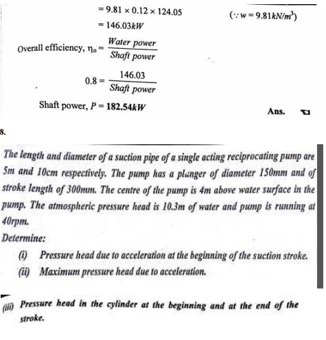
Over all efficiency of a pump (h ) = Fluid power output / Power input to the shaft = rgHQ / P
Type number or Specific speed of pump, nS = NQ1/2 / (gH)3/4 (it is a dimensionless number)
Centrifugal pump Performance
In the volute of the centrifugal pump, the cross section of the liquid path is greater than in the impeller, and in an ideal frictionless pump the drop from the velocity V to the lower velocity is converted according to Bernoulli's equation, to an increased pressure. This is the source of the discharge pressure of a centrifugal pump.
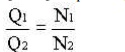
If the speed of the impeller is increased from N1 to N2 rpm, the flow rate will increase from Q1 to Q2 as per the given formula:
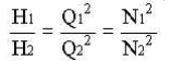
The head developed(H) will be proportional to the square of the quantity discharged, so that
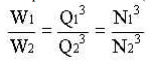
The power consumed(W) will be the product of H and Q, and, therefore
These relationships, however, form only the roughest guide to the performance of centrifugal pumps.
Characteristic curves
Pump action and the performance of a pump are defined interms of their characteristic curves. These curves correlate the capacity of the pump in unit volume per unit time versus discharge or differential pressures. These curves usually supplied by pump manufacturers are for water only.
These curves usually shows the following relationships (for centrifugal pump).
· A plot of capacity versus differential head. The differential head is the difference in pressure between the suction and discharge.
· The pump efficiency as a percentage versus capacity.
· The break horsepower of the pump versus capacity.
The net poisitive head required by the pump versus capacity. The required NPSH for the pump is a characteristic determined by the manufacturer.
Centrifugal pumps are usually rated on the basis of head and capacity at the point of maximum efficiency.
RECIPROCATING PUMPS
Working principle
If the mechanical energy is converted into hydraulic energy (or pressure energy) by sucking the liquid into a cylinder in which a piston is reciprocating (moving backwards and forwards), which exerts the thrust on the liquid and increases its hydraulic energy (pressure energy), the pump is known as reciprocating pump
Main ports of a reciprocating pump
1.A cylinder with a piston, piston rod, connecting rod and a crank,
2. Suction pipe
3.Delivery pipe,
4. Suction valve and
5.Delivery valve.
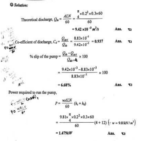
Slip of Reciprocating Pump
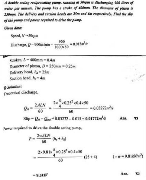
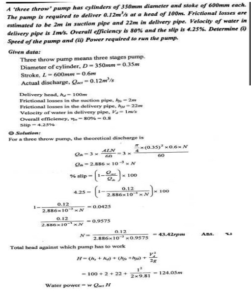
Slip of a reciprocating pump is defined as the difference between the theoretical discharge and the actual discharge of the pump.
Characteristic Curves Of Reciprocatring Pumps
1.According to the water being on contact with one side or both sides of the piston
(i.) Single acting pump (ii.) Double-acting pump
2.According to the number of cylinders provided
(i.) Single acting pump (ii.) Double-acting pump (iii.) Triple-acting pump
Reciprocating pumps Vs centrifugal pumps
The advantages of reciprocating pumps in general over centrifugal pumps may be summarized as follows:
1. They can be designed for higher heads than centrifugal pumps.
2. They are not subject to air binding, and the suction may be under a pressure less than atmospheric without necessitating special devices for priming.
3. They are more flexible in operation than centrifugal pumps.
4. They operate at nearly constant efficiency over a wide range of flow rates.
The advantages of centrifugal pumps over reciprocating pumps are:
1. The simplest centrifugal pumps are cheaper than the simplest reciprocating pumps.
2. Centrifugal pumps deliver liquid at uniform pressure without shocks or pulsations.
3. They can be directly c onnected to motor derive without the use of gea rs or belts.
4. Valves in the discharg e line may be completely closed without injurin g them.
5. They can handle liquid s with large amounts of solids in suspension.
Rotary Pumps
The rotary pump is g ood for handling viscous liquids, nut because of the close tolerances needed, it can not be manufactured large enough to compete with centrifugal pumps for coping with very high flow rates.
Rotary pumps are available in a variety of configurations. • Double lobe pump
• Trible lobe pumps
• Gear pump
• Gear Pumps
• Spur Gear or Extern al-gear pump
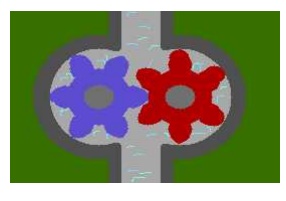
External-gear pump (called as gear pump) consists essen tially of two intermeshing gears which are identical and which are surrounded by a closely fitting casing. One of the gears is driven directly by the prime mover while the other is allowed to rotate freel y. The fluid enters the spaces between the teeth and the casing and moves with the tee th along the outer periphery until it reaches the outlet where it is expelled from the pu mp.
External-gear p umps are used for flow rates up to about 400 m3/hr working against pressures as high as 170 atm. The volumetric efficiency of gear pumps is in the order of 96 percen t at pressures of about 40 atm but decreases a s the pressure rises.
Internal-gear Pump
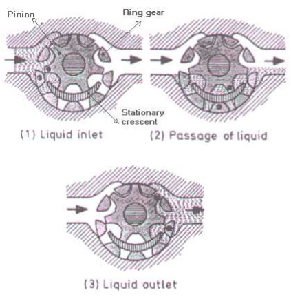
The above figure shows the operation of a internal gear pump. In the internal-gear pump a spur gear, or pinion, meshes with a ring gear with internal teeth. Both gears are inside the casing. The ring gear is coaxial with the inside of the casing, but the pinion, which is externally driven, is mounted eccentrically with respect to the center of the casing. A stationary metal crescent fills the space between the two gears. Liquid is carried from inlet to discharge by both gears, in the spaces between the gear teeth and the crescent.
Lobe pumps
In principle the lobe pump is similar to the external gear pump; liquid flows into the region created as the counter-rotating lobes unmesh. Displacement volumes are formed between the surfaces of each lobe and the casing, and the liquid is displaced by meshing of the lobes. Relatively large displacement volumes enable large solids (nonabrasive) to be handled. They also tend to keep liquid velocities and shear low, making the pump type suitable for high viscosity, shear-sensitive liquids.
Two lobe pump Three lobe pump
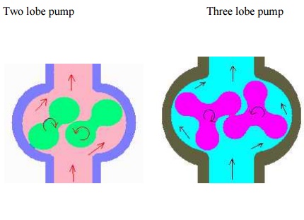
The choice of two or three lobe rotors depends upon solids size, liquid viscosity, and tolerance of flow pulsation. Two lobe handles larger solids and high viscosity but pulsates more. Larger lobe pumps cost 4-5 times a centrifugal pump of equal flow and head.
Selection of Pumps
The following factors influence the choice of pump for a particular operation:
1. The quantity of liquid to be handled: This primarily affects the size of the pump and determines whether it is desirable to use a number of pumps in parallel.
2. The head against which the liquid is to be pumped. This will be determined by the difference in pressure, the vertical height of the downstream and upstream reservoirs and by the frictional losses which occur in the delivery line. The suitability of a centrifugal pump and the number of stages required will largely be determined by this factor.
3. The nature of the liquid to be pumped. For a given throughput, the viscosity largely determines the frictional losses and hence the power required. The corrosive nature will determine the material of construction both for the pump and the packing. With suspensions, the clearance in the pump must be large compared with the size of the particles.
4. The nature of power supply. If the pump is to be driven by an electric motor or internal combustion engine, a high-speed centrifugal or rotary pump will be preferred as it can be coupled directly to the motor.
5. If the pump is used only intermittently, corrosion troubles are more likely than with continuous working.
Applications
The handling of liquids which are particularly corrosive or contain abrasive solids in suspension, compressed air is used as the motive force instead of a mechanical pump.