Definition:
Radiation is the energy transfer across a system boundary due to a T, by the mechanism of photon emission or electromagnetic wave emission.
Because the mechanism of transmission is photon emission, unlike conduction and convection, there need be no intermediate matter to enable transmission.
The significance of this is that radiation will be the only mechanism for heat transfer whenever a vacuum is present.
Electromagnetic Phenomena.
We are well acquainted with a wide range of electromagnetic phenomena in modern life. These phenomena are sometimes thought of as wave phenomena and are, consequently, often described
in terms of electromagnetic wave length, λ. E shown below:
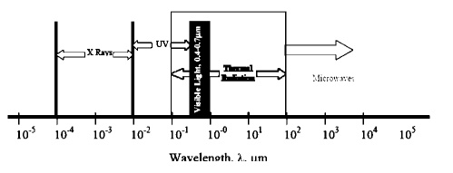
One aspect of electromagnetic radiation is that the related topics are more closely associated with optics and electronics than with those normally found in mechanical engineering courses. Nevertheless, these are widely encountered topics and the student is familiar with them through every day life experiences.
From a viewpoint of previously studied topics students, particularly those with a background in mechanical or chemical engineering, will find the subject of Radiation Heat Transfer a little unusual. The physics background differs fundamentally from that found in the areas of continuum mechanics. Much of the related material is found in courses more closely identified with quantum physics or electrical engineering, i.e. Fields and Waves. At this point, it is important for us to recognize that since the subject arises from a different area of physics, it will be important that we study these concepts with extra care.
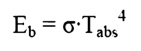
Stefan-Boltzman Law
Both Stefan and Boltzman were physicists; any student taking a course in quantum physics will
become well acquainted with Boltzman’s work as he to the field. Both were contemporaries of Einstein so we see that the subject is of fairly recent
vintage. (Recall that the basic equation for convection heat transfer is attributed to Newton)
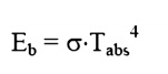
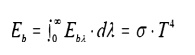
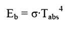
where: Eb = Emissive Power, the gross energy emitted from an ideal surface per unit area, time.
⋅ -8 2⋅4
σ = Stefan Boltzman10W/mK constant, 5.67
Tabs = Absolute temperature of the emitting surface, K.
Take particular note of the fact that absolute temperatures are used in Radiation. It is suggested, as a matter of good practice, to convert all temperatures to the absolute scale as an initial step in all radiation problems.
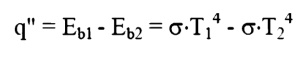
You will notice that the equation does not in the emissive power. The relationship between these terms is as follows. Consider two infinite
plane surfaces, both facing one another. Both surfaces are ideal surfaces. One surface is found to be at temperature, T1, the other at temperature, T2. Since both temperatures are at temperatures above absolute zero, both will radiate energy as described by the Stefan-Boltzman law. The heat flux will be the net radiant flow as given by:
Plank’s Law
While the Stefan-Boltzman law is useful for studying overall energy emissions, it does not allow
us to treat those interactions, which deal specifically with wavelength, overcome by another of the modern physicists, Max Plank, who developed a relationship for wave-based emissions.
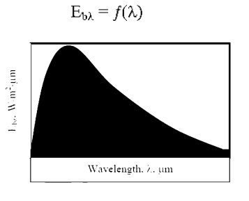
We haven’t yet defined the bλ.MonochromaticAnimplicitdefinitionis Emi
provided by the following equation:
We may view this equation graphically as follows:
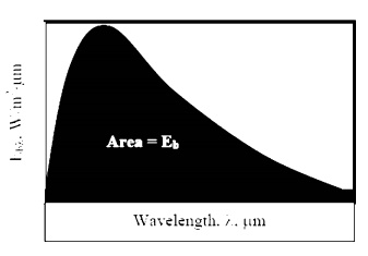
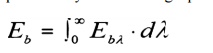
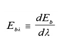
A definition of monochromatic Emissive Power would be obtained by differentiating the integral equation:
The actual form of Plank’s law is:
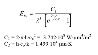
Where: h, co, k are all parameters from quantum physics. We need not worry about their precise definition here.
This equation may be solved at any T, λ to give the value of the monochromatic emissivity at that
that condition. Alternatively, the function may be substituted into the integral
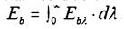
to find the Emissive power for any temperature. While performing this integral by hand is difficult, students may readily evaluate the integral through one of several computer programs, i.e. MathCad, Maple, Mathmatica, etc.
Emission Over Specific Wave Length Bands
Consider the problem of designing a tanning machine. As a part of the machine, we will need to design a very powerful incandescent light source. We may wish to know how much energy is being emitted over the
ultraviolet band (10-4 to 0.4 μm), known to be particularly dangerous.
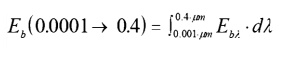
With a computer available, evaluation of this integral is rather trivial. Alternatively, the text books provide a table of integrals. The format used is as follows:
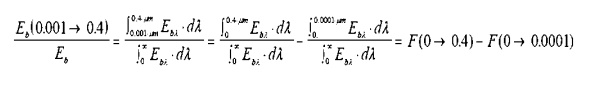
Referring to such tables, we see the last two functions listed in the second column. In the first column is a⋅T. Thisparameter,isfoundbytakingthe productλ of the absolute temperature of
the emitting surface, T, and the upper limit incandescent bulb is designed to operate at a temperature of 2000K. Reading from the table:
λ.,
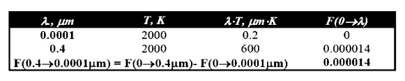
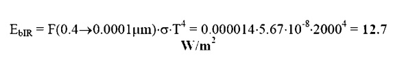
This is the fraction of the total energy emitted which falls within the IR band. To find the absolute energy emitted multiply this value times the total energy emitted:
Solar Radiation
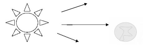
The magnitude of the energy leaving the Sun varies with time and is closely associated with such factors as solar flares and sunspots. Nevertheless, we often choose to work with an average value. The energy leaving the sun is emitted outward in all directions so that at any particular distance from the Sun we may imagine the energy being dispersed over an imaginary spherical area. Because this area increases with the distance squared, the solar flux also decreases with the distance squared. At the average distance between Earth and Sun this heat flux is 1353 W/m2, so that the average heat flux on any object in Earth orbit is found as:
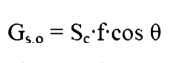
Where Sc = Solar Constant, 1353 W/m2
f = correction factor for eccentricity in Earth Orbit, (0.97<f<1.03)
θ = Angle of surface from normal to Sun.
Because of reflection and absorption in the reduced at ground level. Nevertheless, this value gives us some opportunity to estimate the
potential for using solar energy, such as in photovoltaic cells.
Some Definitions
In the previous section we introduced the Stefan-Boltzman Equation to describe radiation from an ideal surface.
This equation provides a method of determining the total energy leaving a surface, but gives no indication of the direction in which it travels. As we continue our study, we will want to be able to calculate how heat is distributed among various objects.
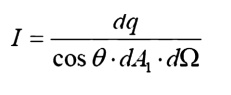
For this purpose, we will introduce the radiation intensity, I, defined as the energy emitted per unit area, per unit time, per unit solid angle. Before writing an equation for this new property, we will need to define some of the terms we will be using.
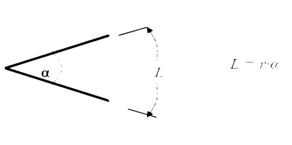
Angles and Arc Length
We are well accustomed to thinking of an angle as a two dimensional object. It may be used to find an arc length:
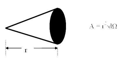
Solid Angle
We generalize the idea of an angle and an arc length to three dimensions and define a solid
angle, Ω, which like the standard angle has n the radius squared will have dimensions of length squared, or area, and will have the magnitude of the encompassed area.
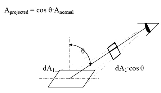
Projected Area
The area, dA1, as seen from the prospective o to the surface, will appear somewhattermed thesmaller projected area.
Intensity
The ideal intensity, Ib, may now be defined as the energy emitted from an ideal body, per unit projected area, per unit time, per unit solid angle.
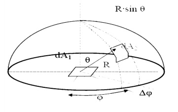
Spherical Geometry
Since any surface will emit radiation outward in all directions above the surface, the spherical coordinate system provides a convenient tool for analysis. The three basic coordinates shown are
R, φ, and θ, representing the radial, azimuth
In general dA1 will correspond to the emitting surface or the source. The surface dA2 will correspond to the receiving surface or the target. Note that the area proscribed on the hemisphere, dA2 , may be written as:
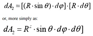
Recalling the definition of the solid angle,
dA = R2·dΩ
we find that:
dΩ =sin2R θ·dθ·dφ
Real Surfaces
Thus far we have spoken of ideal surfaces, i.e. those that emit energy according to the Stefan-Boltzman law:
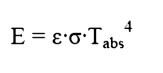
Real surfaces have emissive powers, E, which are somewhat less than that obtained theoretically
by Boltzman. To account for this reduction, w
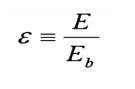
so that the emissive power from any real surface is given by:
Receiving Properties
Targets receive radiation in one of three ways; they absorption, reflection or transmission. To account for these characteristics, we introduce three additional properties:
• Absorptivity, α, the fraction of incident r
• Reflectivity, ρ, the fraction of incident r
Transmissivity,onofincident radiationτ, thetransmittedfracti.
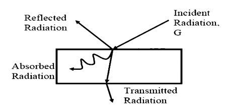
We see, from Conservation of Energy, that:
α + ρ + τ = 1
In this course, we will deal with only opaque
α + ρ = 1 Opaque Surfaces
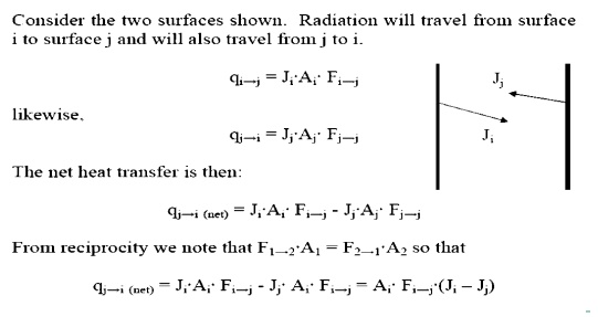
SHAPE FACTOR:
Net Exchange Between Surfaces
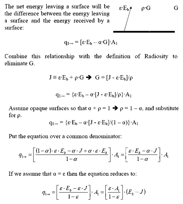
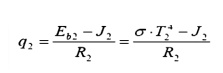
Net Energy Leaving a Surface
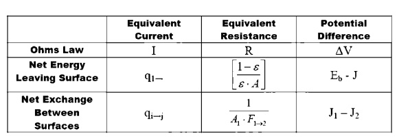
ELECTRICAL ANALOGY :
Electrical Analogy for Radiation
We may develop an electrical analogy for radiation, similar to that produced for conduction. The two analogies should not be mixed: they have different dimensions on the potential differences, resistance and current flows.
RADIATION SHIELDS ;
Insulated surfaces. In steady state heat transfer, a surface cannot receive net energy if it is insulated. Because the energy cannot be stored by a surface in steady state, all energy must be re-radiated back into the enclosure. Insulated surfaces are often termed as re-radiating surfaces.
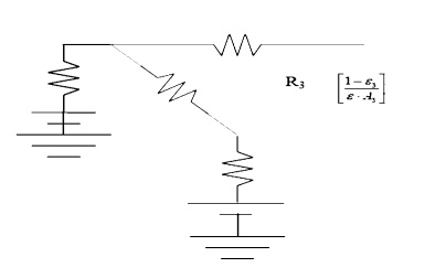
Electrically cannot flow through a battery if it is not grounded.
Surface 3 is not grounded so that the battery and surface resistance serve no purpose and are removed from the drawing.
• Black surfaces: A black, or ideal surface,
In this case the nodal Radiosity and emissive power will be equal.
This result gives some insight into the physical meaning of a black surface. Ideal surfaces radiate at the maximum possible level. Non-black surfaces will have a reduced potential, somewhat like a battery with a corroded terminal. They therefore have a reduced potential to cause heat/current flow.
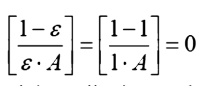
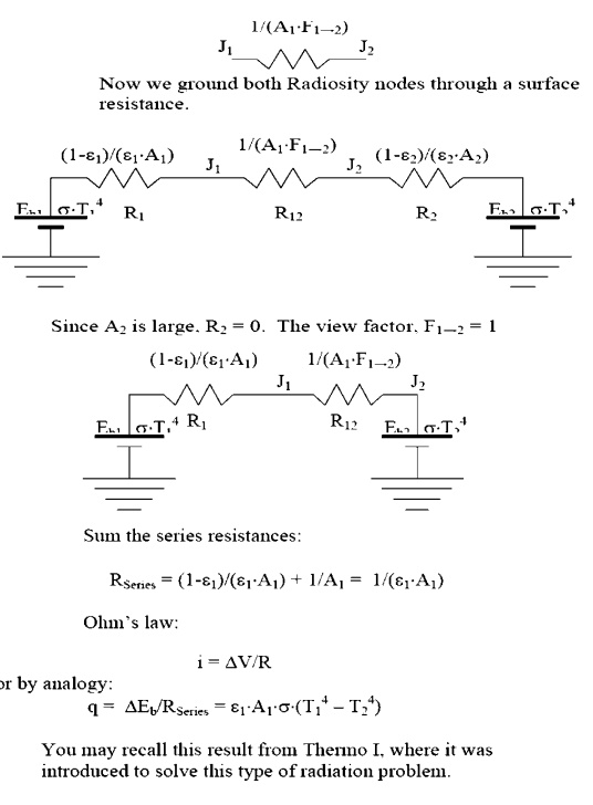
• Largeces: Surfacessurfahaving a large surface area will behave as black surfaces, irrespective of the actual surface properties:
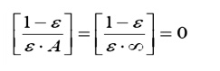
Physically, this corresponds to the characteristic of large surfaces that as they reflect energy, there is very little chance that energy will strike the smaller surfaces; most of the energy is reflected back to another part of the same large surface. After several partial absorptions most of the energy received is absorbed.
Consider the case of an object, 1, placed inside a large enclosure, 2. The system will consist of two objects, so we proceed to construct a circuit with two radiosity nodes
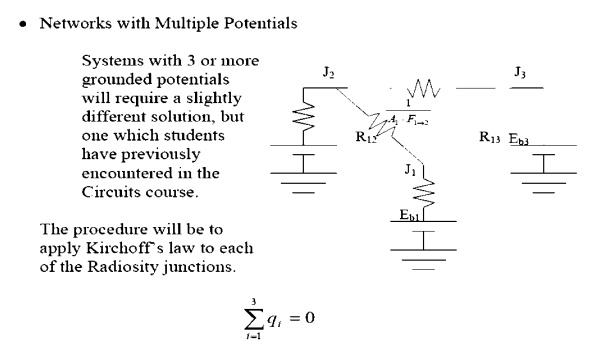
In this example there are three junctions, so we will obtain three equations. This will allow us to solve for three unknowns.
Radiation problems will generally be presented on one of two ways:
1. The surface net heat flow is given and the surface temperature is to be found.
2. The surface temperature is given and the net heat flow is to be found.
Returning for a moment to the coal grate furnace, let us assume that we know (a) the total heat being produced by the coal bed, (b) the temperatures of the water walls and (c) the temperature of the super heater sections.
Apply Kirchoff’s law about node 1, for the co
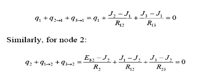
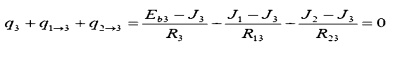
(Note how node 1, with a specified heat input, is handled differently than node 2, with a specified temperature.
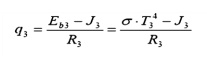
And for node 3:
The three equations must be solved simultaneously. Since they are each linear in J, matrix methods may be used:
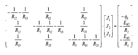
The matrix may be solved for the individual Radiosity. Once these are known, we return to the electrical analogy to find the temperature of surface 1, and the heat flows to surfaces 2 and 3.
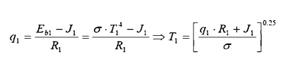
Surface 1: Find the coal bed temperature, given the heat flow:
Surface 2: Find the water wall heat input, given the water wall temperature:
Surface 3: (Similar to surface 2) Find the water wall heat input, given the water wall temperature: