
SELECTION OF DISPLACEMENT, POSITION & PROXIMITY SENSOR:
Size of the displacement (mm)
Displacement type (Linear or angular)
Resolution required
Accuracy Required
Material of the object
Cost
DISPLACEMENT SENSORS
Displacement sensors are con tact type sensor
Types of Displacement sensors:
Potentiometer
Strain gauge
Capacitive sensors
Linear variable differential tr ansformer
POTENTIOMETER
PRINCIPLE:
It works on variable resistance transduction principle
Linear or Rotary potentiometer is a variable resistance displacement tran sducer which uses the variable resistance transduction prin ciple in which the displacement or rotation isco nverted into a potential differencedue to the movement ofsli ding contact over a resistiveelement
CONSTRUCTION & WORKING:
A resistor with three terminals.
Two end terminal & one mid dle terminal (wiper)
Two end terminal are connected to external input voltage
One middle and one end term inal as output voltage
The slider determines the ma gnitude of the potential difference developed
Characteristics:
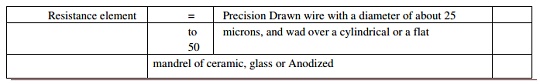
Resistance element = Precision Drawn wire with a diameter o f about 25
to microns, and wad over a cylindrical or a flat
50
mandrel of ceramic, glass or Anodized
Aluminium. 2 mm to 500 mm in case of linear pot.
= For high resolution, w ire is made by using ceramic (cermet) or conductive plastic film d ue to low noise levels.
Wipers (Sliders) = Tempered phosphor bronze, beryllium copper or other precious alloys.
Wire Material = Strong, ductile and protected from surfa ce corrosion by enamelling or oxidation.
Materials &e alloys of copper nickel, Nickel chromium, and silver palladium.
= Resistivity of wire ranges from 0.4 µΩm to 13 µΩm
Resistance range = 20Ω to 200KΩ and for plastic 500Ω to 80KΩ
Accuracy = Higher temperature coefficient of resistance than the wire and so temperature changes have a greater effect Accuracy.
STRAIN GAUGE:
Strain gauges are passive type resistance sensor whose electrical resistance change when it is
stretched or compressed (mechanically strained) under the application of force.
The electrical resistance is changed due to the change in length (increases) and cross sectional area
(decreases) of the strain gauge.
This change in resistance is then usually converted into voltage by connecting one, two or four
similar gauges as an arm of a Wheatstone bridge (known as Strain Gauge Bridge) and applying excitation to
the bridge. The bridge output voltage is then a measure of strain, sensed by each strain gauge.
Unbonded Type Strain Gauges:
In unbonded type, fine wire filaments (resistance wires) are stretched around rigid and electrically insulated pins on two frames.
One frame is fixed and the other is movable.
The frames are held close with a spring loaded mechanism.
Due to the relative motion between two frames, the resistance wires are strained.
This strain is then can be detected through measurement of the change in electrical resistance since they are not cemented with the surfaces, they can be detached and reused.
Bonded Type Strain Gauges:
Bonded type strain gauges consists of resistance elements arranged in the form of a grid of fine wire, which is cemented to a thin paper sheet or very thin Bakelite sheet, and covered with a protective sheet of paper or thin Bakelite.
The paper sheet is then bonded to the surface to be strained. The gauges have a bonding material which acts an adhesive material during bonding process of a surface with the gauge element.
Classification of Bonded Type Strain Gauges:
Fine wire gauges
Metal foil gauges
Semiconductor filament type
Fine Wire Gauges:
Wire of 3 to 25 microns diameter is arranged in the form of grid consisting of parallel loops
Metal Foil Gauges:
A thin foil of metal, deposited as a grid pattern onto a plastic backing material using polyimide
Foil pattern is terminated at both ends with large metallic pads Entire gauge size 5- 15mm
Adhesive directly bonded to the gauge usually epoxy
Semiconductor Filament Type:
The gauges are produced in wafers from silicon or germanium crystals
Special impurities such as boron is added
It is mounted on an epoxy resin backing with copper on nickel leads
Filament about 0.05mm thick 0.25mm wide and 1.25 to 12mm length
CAPACITIVE SENSORS:
It is used for measuring, displacement, velocity, force etc..
Principle:
It is passive type sensors in which equal and opposite charges are generated on the plates due to voltage applied across the plate which is separated by dielectric material.
Formula:
By Changing the Distance between Two Plates:
The displacement is measured due to the change in capacitance
By Varying the Area of Overlap:
The displacement causes the area of overlap to vary
The capacitance is directly proportional to the area of the plates and varies linearly with changes in the displacement between the plates
By Varying the Dielectric Constant:
The change in capacitance can be measured due to change in dielectric constant as a result of displacement.
When the dielectric material is moved due to the displacement, the material causes the dielectric constant to vary in the region where the two electrodes are separated that results in a charge in capacitance.
Push Pull Sensor:
Push pull displacement sensor is used to overcome the non-linearity error.
The sensor consists of three plates with the upper pair forming one capacitor and the lower pair forming another capacitor.
The displacement moves central plate between the two other plates.
If the central plate moves downwards.
The plate separation of the upper capacitor increases and the separation of the lower one decreases.
LINEAR VARIABLE DIFFERENTIAL TRANSFORMER:
It consists of three symmetrically spaced coils.
The centre coil is primary coil and other two are secondary coil
Secondary coils are connected in series opposition and equally positioned with respect to primary coil
The output voltage is proportional to the displacement of the core from null position
PROXIMITY SENSORS
Proximity sensors are non – contact type sensor.
Types of Proximity Sensor:
Eddy current proximity sensor
Inductive proximity sensor
Pneumatic proximity sensor
Proximity switches
EDDY CURRENT PROXIMITY SENSOR:
PRINCIPLE:
When a coil is supplied with alternating current, an alternating magnetic field is produced which
induces an EMF on it. If there is a metal near to this alternating magnetic field, on EMF is induced in it.
The EMF cause current to flow. This current flow is eddy current.
CONSTRUCTION & WORKING:
It has two identical coils.
One reference coil & another sensing coil which senses the magnetic current in the object. Eddy current start to flow due to AC(conducting object) close to sensor
Eddy current produce a magnetic field to oppose the magnetic field generated by sensing coil. Due to this opposition reduction flux is created. To detect 0.001mm
INDUCTIVE PROXIMITY SENSORS:
It consists of coil wound round a core.
Metal is close to coil Inductance changes occurs.
It is suitable for ferrous metals
PNEUMATIC PROXIMITY SWITCHES:
It is suitable for sensing non conducting materials
Air is allowed to escape from the front side of the sensor.
When there is no object air escapes freely.
When there is an object, the escaping air is blocked and return backed to system.
It is used to measure the range 3mm to 12mm
PROXIMITY SWITCHES:
It is used in robotics for sensing elements
It is also used in NC machines, material handling systems and assembly lines. Micro switch
Reed switch
Photo sensitive switch Mechanical switch
Micro Switch:
It is limit switch operated by levers, rollers & cams
It is switch which requires physical contact and small force to close the contacts. Example a belt conveyor.
Reed Switch:
It is a non – contact proximity switch that consists of two magnetic switch contacts enclosed in a glass tube fined with an inert gas.
When magnet is closed switch is operated. Used for high speed applications.
Photo Sensitive Devices:
It is used to sense opaque object.
Photo detector receives a beam of light produced by the LED.
Object is passed the beam gets broken or reflected when is detected.