
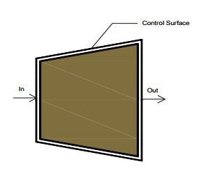
The Steady-state Flow Process
When a flow process is satisfying the following conditions, it is known as a steady flow process.
1. The mass and energy content of the control volume remains constant with time.
2. The state and energy of the fluid at inlet, at the exit and at every point within the control volume are time independent.
3. The rate of energy transfer in the form of work and heat across the control surface is constant with time.
Therefore for a steady flow process

This equation is commonly known as steady flow energy equation (SFEE).
Application of SFEE
SFEE governs the working of a large number of components used in many engineering practices. In this section a brief analysis of such components working under steady flow conditions are given and the respective governing equations are obtained.
Turbines
Turbines are devices used in hydraulic, steam and gas turbine power plants. As the fluid passes through the turbine, work is done on the blades of the turbine which are attached to a shaft. Due to the work given to the blades, the turbine shaft rotates producing work.
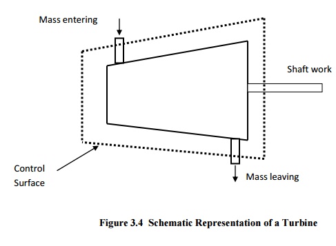
General Assumptions
1. Changes in kinetic energy of the fluid are negligible
2. Changes in potential energy of the fluid are negligible.
[Q-W ]=m[(h2 -h1 )]
Compressors
Compressors (fans and blowers) are work consuming devices, where a low-pressure fluid is compressed by utilising mechanical work. Blades attached to the shaft of the turbine imparts kinetic energy to the fluid which is later converted into pressure energy.
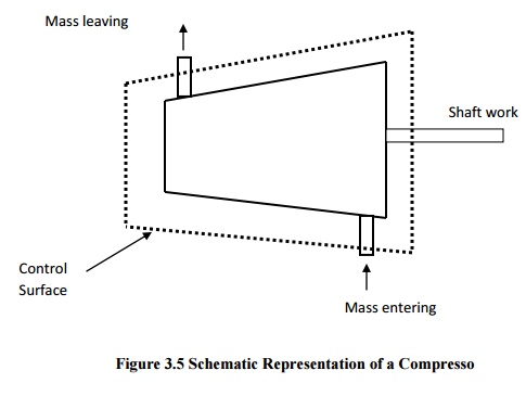
General Assumptions
1. Changes in the kinetic energy of the fluid are negligible
2. Changes in the potential energy of the fluid are negligible
Governing Equation
Applying the above equations SFEE becomes
[Q-W ]=m[(h2 -h1 )]
Pumps
Similar to compressors pumps are also work consuming devices. But pumps handle incompressible fluids, whereas compressors deal with compressible fluids.
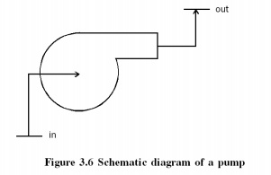
General Assumptions
1. No heat energy is gained or lost by the fluids;
2. Changes in kinetic energy of the fluid are negligible.
Governing Equation
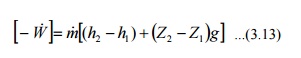
As the fluid passes through a pump, enthalpy of the fluid increases, (internal energy of the fluid remains constant) due to the increase in pv (flow energy). Increase in potential energy of fluid is the most important change found in almost all pump applications.
Nozzles
Nozzles are devices which increase the velocity of a fluid at the expense of pressure. A typical nozzle used for fluid flow at subsonic* speeds is shown in Figure 3.7.
General Assumptions
1. In nozzles fluids flow at a speed which is high enough to neglect heat lost or gained as it crosses the entire length of the nozzle. Therefore, flow through nozzles can be regarded as adiabatic. That is =0.
2. There is no shaft or any other form of work transfer to the fluid or from the fluid; that is
=0.
Changes in the potential energy of the fluid are negligible.
Governing Equation
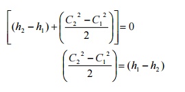
Diffusers
Diffusers are (reverse of nozzles) devices which increase the pressure of a fluid stream by reducing its kinetic energy.
General Assumptions
Similar to nozzles, the following assumptions hold good for diffusers.
1. Heat lost or gained as it crosses the entire length of the nozzle. Therefore, flow through nozzles can be regarded as adiabatic. That is Q = 0
2. There is no shaft or any other form of work transfer to the fluid or from the fluid; that is = 0.
3. Changes in the potential energy of the fluid are negligible
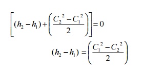
Governing Equation
Heat Exchangers
Devices in which heat is transferred from a hot fluid stream to a cold fluid stream are known as heat exchangers.
Throttling
A throttling process occurs when a fluid flowing in a line suddenly encounters a restriction in the flow passage. It may be
· a plate with a small hole as shown in Figure 3.10 (a)
· a valve partially closed as shown in Figure 3.10 (b)
· a capillary tube which is normally found in a refrigerator as shown in Figure 3.10 (c)
· a porous plug as shown in Figure 3.10 (d)

First Law for a Cyclic Process
In a cyclic process the system is taken through a series of processes and finally returned to its original state. The end state of a cyclic process is identical with the state of the system at the beginning of the cycle. This is possible if the energy level at the beginning and end of the cyclic process are also the same. In other words, the net energy change in a cyclic process is zero.
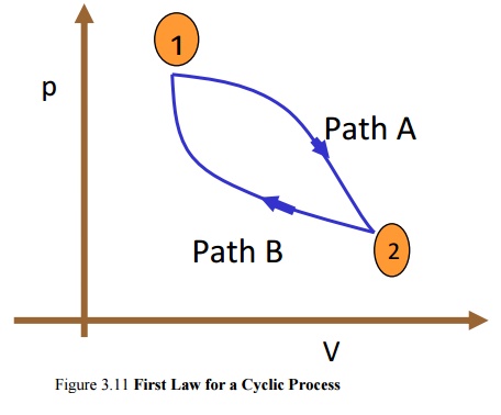
Figure 3.11 First Law for a Cyclic Process
Consider a system undergoing a cycle consisting of two processes A & B as shown in Figure 3.11 Net energy change
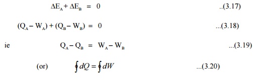
Hence for a cyclic process algebraic sum of heat tranfers is equal to the algebraic sum of work transfer.
This was first proved by Joule, based on the experiments he conducted between 1843 and 1858, that were the first quantitative analysis of thermodynamic systems.
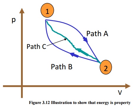
Energy is a property of a system
Consider a system undergoing a process from state1 to state2 along path A as shown in Figure 3.12. Let the system be taken back to the initial state 1 along two possible paths B and C. Process A, combined separately with process B and C forms two possible cycles.
Cycle 1A2B1
QA +QB =[WA +WB]
QA -WA =-[QB -WB]
E = - DE D ...(3.21)
Cycle 1A2C1
QA +QC =[WA +WC]
QA -WA =-[QC -WC]
DEA = - DEC ...(3.22)
From Equation (3.21) and (3.22) it can be concluded that energy change in path B and path C are equal and hence energy is a point function depending only on the end states.
It has been already shown that all the properties are point functions and hence energy is also a property of the system.
Specific Heat at Constant Volume and at Constant Pressure
Specific heat at constant volume of a substance is the amount of heat added to rise the temperature of unit mass of the given substance by 1 degree at constant volume
From first law for a stationary closed system undergoing a process
dQ =pdV + dU or dq =pdv + du
For a constant volume process
dQ =dU or dq =du
du =C dT ...(3.23)
Similarly specific heat at constant pressure is the quantity of heat added to rise the temperature of unit mass of the given substance by 1 degree at constant pressure
where dQ =pdV + dU
=pdV + d(H -PV)
dQ = pdV + dH -Vdp -pdV dQ =dH -Vdp
For a constant pressure process dp =0
Hence dQ =dH or dq =dh
\
or dh =CpdT
· The difference in specific heats Cp -Cv =R
· The ratio of sp. heat g =Cp/Cv
· Since h and u are properties of a system, dh =CpdT and du=CvdT, for all processes.
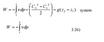
Work Interaction in a Reversible Steady Flow Process
In a steady flow process the work interaction per unit mass between an open system and the surroundings can be expressed in differential form as
dq - dw - dh + CdC + gdz
dw - dq - (dh + CdC +gdz)
dq - du + pdv (or) dh - vdp
dw - dh - vdp - (dh + CdC + gdz)
- vdp - (CdC + gdz)
For a stationary
First law for an open system under unsteady flow conditions
Many processes of engineering interest involve unsteady flow, where energy and mass
content of the control volume increase or decrease.
Example for such conditions are:
1) Filling closed tanks with a gas or liquid.
2) Discharge from closed vessels.
3) Fluid flow in reciprocating equipments during an individual cycle.
To develop a mathematical model for the analysis of such systems the following assumptions are
made.
instant of time the state is uniform throughout the entire control volume.
3) The state of the mass crossing each of the areas of flow on the control surface is constant with time although the mass flow rates may be time varying.
Unlike in steady flow system, duration of observation Dt plays an important role in transient analysis. Let mass of the working fluid within the control volume before and after the observation be m1 and m2 respectively. Applying mass balance we get,
(m2 -m1)CV =Smi -Sm0 ...(3.27)
Where ∑mi is the mass entered the control volume during the interval Dt seconds.
∑m0 is the mass left the control volume during the interval Dt seconds.
By applying energy balance we get,
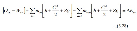
Where ECV is the change in energy content of the control volume in Dt seconds.
QCV is the heat energy entered into the control volume in Dt seconds.
WCV is the work energy left the control volume in Dt seconds.
hi & h0 are specific enthalpy of the inlet and outlet streams respectively.
are the kinetic energy of the inlet and outlet streams respectively.
Zig & Z0g are the potential energy of inlet and outlet streams respectively.
Perpetual Motion Machine – I
An engine which could provide work transfer continuously without heat transfer is known as perpetual motion machine of first kind. It is impossible to have such an engine as it violates first law of thermodynamics.