Hydraulic Machines are defined as those machines which convert either hydraulic energy (energy possessed by water) into mechanical energy (which is further converted into electrical energy) or mechanical energy into hydraulic energy.
The hydraulic machines, which convert the hydraulic energy into mechanical energy, are called turbines.
Turbines are defined as the hydraulic machines which convert hydraulic energy into mechanical energy. This mechanical energy is used in running an electric generator which is directly coupled to the shaft of the turbine. Thus the mechanical energy is converted into electrical energy. The electric power which is obtained from the hydraulic energy (energy of water) is known as Hydro- electro power.
In our subject point of view, the following turbines are important and will be discussed one by one.
1. Pelton wheel
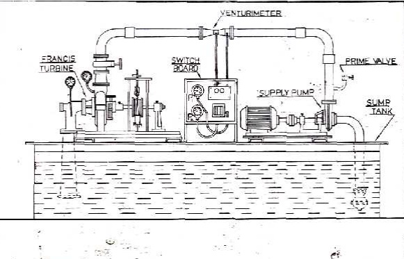
2. Francis turbine
3. Kaplan turbine
Concept
Turbines are defined as the hydraulic machines which convert hydraulic energy into mechanical energy. This mechanical energy is used in running an electric generator which is directly coupled to the shaft of the turbine
FLUID TYPES OF TURBINE
Water Hydraulic Turbine
Steam Steam Turbine
Froen Vapour Turbine
Gas or air Gas Turbine
Wind Wind Mills
CLASSIFICATION OF HYDRAULIC TURBINES
1. According to the action of the water flowing
2. According to the main direction of flow of water
3. According to the head and quality of water required
4. According to the specific speed
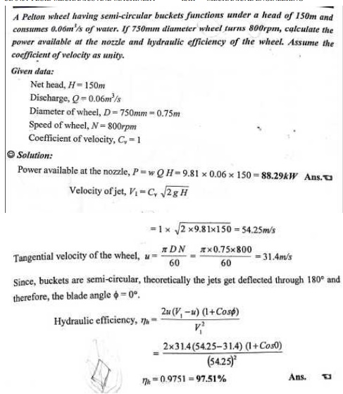
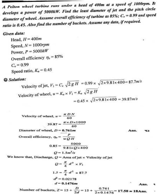
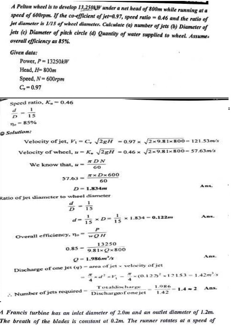
HEAD AND EFFICIANCES OF PELTON WHEEL
1. Gross head
2. Effective or Net head
3. Water and Bucket power
4. Hydraulic efficiency
5. Mechanical efficiency
6. Volume efficiency
7. Overall efficiency
IMPULSE TURBINE
In an impulse turbine, all the energy available by water is converted into kinetic energy by passing a nozzle. The high velocity jet coming out of the nozzle then impinges on a series of buckets fixed around the rim of a wheel.
Tangential Flow Turbine, Radial And Axial Turbines
1. Tangential flow turbine
In a tangential flow turbine, water flows along the tangent to the path of runner. E.g. Pelton wheel
2. Radial flow turbine
In a radial flow turbine, water flows along the radial direction and mainly in the plane normal to the axis of rotation, as it passes through the runner. It may be either inward radial flow type or outward radial flow type.
3. Axial flow turbine
In axial flow turbines, water flows parallel to the axis of the turbine shaft. E.g. kaplan turbine
4. Mixed flow turbine
In a mixed flow turbine, the water enters the blades radiallsy and comes out axially and parallel to the turbine shaft .E.g. Modern Francis turbine.
In our subject point of view, the following turbines are important and will be discussed one by one
1. Pelton wheel
2. Francis turbine
3. Kaplan turbine
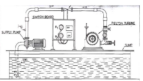
PELTON WHEEL OR PELTON TURBINE
The Pelton wheel is a tangential flow impulse turbine and now in common use. Leston A Pelton, an American engineer during 1880,develops this turbines. A pelton wheel consists of following main parts.
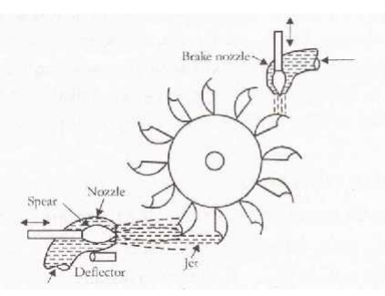
1. Penstock
2. Spear and nozzle
3. Runner with buckets
4. Brake nozzle
5. Outer casing
6. Governing mechanism
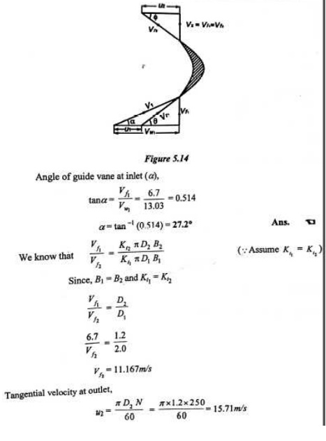
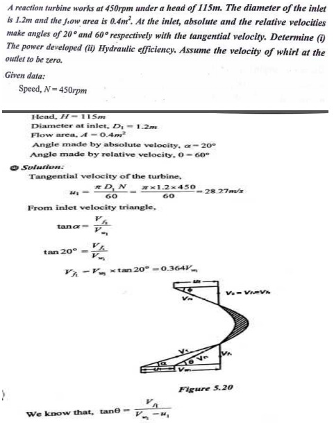
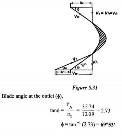
1 VELOCITY TRIANGLES, WORKDONE, EFFICIENCY OF PELTON
WHEEL INLET AND OUTLET VECTOR DIAGRAMS
Let V = Velocity of the jet
u = Velocity of the vane (cups) at the impact point u
= DN/ 60
where D = Diameter of the wheel corresponding to the impact point = Pitch circle diameter.
At inlet the shape of the vane is such that the direction of motion of the jet and the vane is the same.
i.e., Ȑ= 0, ș= 0
Relative velocity at inlet
Vr = V —u
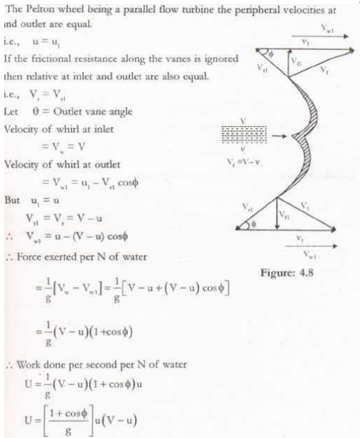
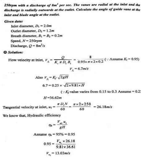
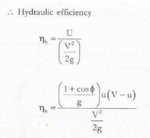
Hydraulic efficiency
This is the ratio of the workk done per second per head at inlet to the turbine.
Energy head at inlet = V2/2g
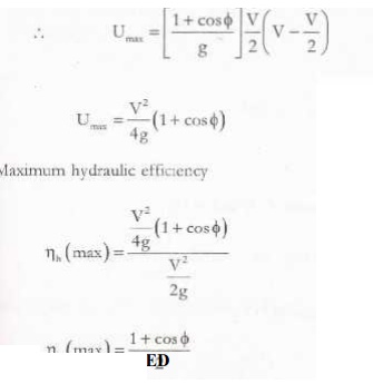
Condition for maximum hydraulic efficiency
For a given jet velocity for efficiency to be maximum, word done should be maximum
Work done per second per N of water
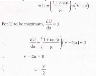
Hence for the condition of maximum hydraulic efficiency, the peripheral speed of the turbine should reach one half the jet speed.
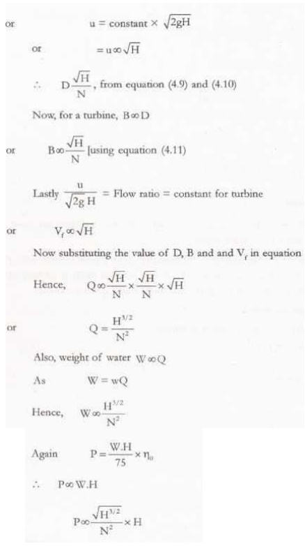
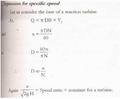
SPECIFIC SPEED
[ The speed of any water turbine is represented by N rpm. A turbine has speed, known as specific speed and is represented by N
‘ Specific speed of a water turbine in the speed at which a geometrically similar turbine would run if producing unit power (1 kW) and working under a net head of 1 m. Such a turbine would be an imaginary one and is called specific turbine.
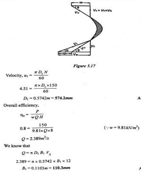
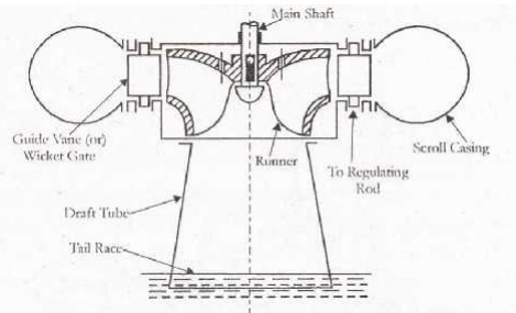
FRANCIS TURBINE
Francis turbine is an i nward flow reaction turbine. It is developed b y the American engineer James B. Francis. In the earlier stages, Francis turbine had a purely ra dial floe runner. But the modern Francis turbine is a mixed flow reaction turbine in which the water enters the runner radially at its outer peripher y and leaves axially at its centre. This arrangement provides larger discharge area with prescribed diameter of the runner. The main parts such as
1. Penstock
2. Scroll or Spiral Casing
3. Speed ring or Stay ring
4. Guide vanes or Wickets gat es
5. Runner and runner blades
6. Draft tube
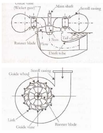
KAPLAN TURBINE
A Kaplan turbine is an axial flow reaction turbine which was developed by Austrian engineer V. Kaplan. It is suitable for relatively low heads. Hence, it requires a large quantity of water to develop large power. The main parts of Kaplan turbine, they are
1. Scroll casing
2. Stay ring
3. Guide vanes
4. Runner
5. Draft tube
PERFORMANCE OF TURBINES
Turbines are often required to work under varying conditions of head, speed, output and gate opening. In order to predict their behavior, it is essential to study the performance of the turbines under the varying conditions. The concept of unit quantities and specific quantities are required to
The behavior of a turbine is predicted working under different conditions.
Comparison is made between the performance of turbine of same type but of different sizes.
The performance of turbine is compared with different types.
DRAFT TUBE
The pressure at the exit of the runner of a reaction turbine is generally less than atmospheric pressure. Thus the water at the exit of the runner cannot be directly discharged to the tail race. A pipe o gradually increasing area is used for discharging water form the exit of the turbine to the tail race. This pipe of gradually increasing area is called a draft tube.
SPECIFIC SPEED
Homologus units are required in governing dimensionless groups to use scaled models in designing turbomachines, based geometric similitude.
Specific speed is the speed of a geometrically similar turbine, which will develop unit power when working under a unit head. The specific speed is used in comparing the different types of turbines as every type of turbine has different specific speed. In S.I. units, unit power is taken as one Kw and unit as one meter.
GOVERNING OF TURBINES
All the modern hydraulic turbines are directly coupled to the electric generators. The generators are always required to run at constant speed irrespective of the variations in the load. It is usually done by regulating the quantity of water flowing through the runner in accordance with the variations in the load. Such an operation of regulation of speed of turbine runner is known as governing of turbine and is usually done automatically by means of a governor.
Applications
1. To produce the power by water.
GLOSSARY
HP –Horse power
KW- Kilo watts