
Interrupt Programming:
What Events Can Trigger interrupts, and where do they go?
The following events will cause an interrupt:
· Timer 0 Overflow.
· Timer 1 Overflow.
· Reception/Transmission of Serial Character.
· External Event 0.
· External Event 1.
To distinguish between various interrupts and executing different code depending on what interrupt was triggered 8051may be jumping to a fixed address when a given interrupt occurs.
Table 5.5 Interrupt handling
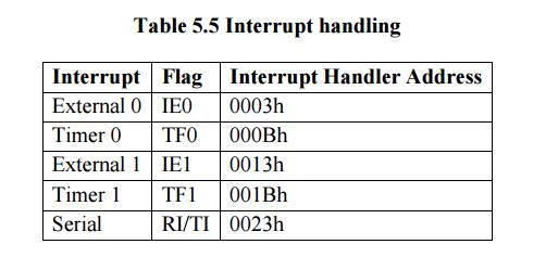
If Timer 0 overflows (i.e., the TF0 bit is set), the main program will be temporarily suspended and control will jump to 000BH if we have code at address 0003H that handles the situation of Timer 0 overflowing.
ü Setting Up Interrupts
By default at power up, all interrupts are disabled. Even if, for example, the TF0 bit is set, the 8051 will not execute the interrupt. Your program must specifically tell the
8051 that it wishes to enable interrupts and specifically which interrupts it wishes to enable. Your program may enable and disable interrupts by modifying the IE SFR (A8h):
Table 5.6 Interrrupt and address
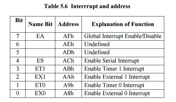
Each of the 8051’sinterrupts has its own bit in the IE SFR. You enable a given interrupt by setting the corresponding bit. For example, if you wish to enable Timer 1 Interrupt, you would execute either:
MOV IE,#08h || SETB ET1
Both of the above instructions set bit 3 of IE, thus enabling Timer 1 Interrupt. Once Timer 1 Interrupt is enabled, whenever the TF1 bit is set, the 8051 will automatically put "on hold" the main program and execute the Timer 1 Interrupt Handler at address 001Bh. However, before Timer 1 Interrupt (or any other interrupt) is truly enabled, you must also set bit 7 of IE.
Bit 7, the Global Interrupt Enable/Disable, enables or disables all interrupts simultaneously. That is to say, if bit 7 is cleared then no interrupts will occur, even if all the other bits of IE are set. Setting bit 7 will enable all the interrupts that have been selected by setting other bits in IE. This is useful in program execution if you have time-critical code that needs to execute. In this case, you may need the code to execute from start to finish without any interrupt getting in the way. To accomplish this you can simply clear bit 7 of IE (CLR EA) and then set it after your time critical code is done.
To enable the Timer 1 Interrupt execute the following two instructions:
SETB ET1
SETB EA
Thereafter, the Timer 1 Interrupt Handler at 01Bh will automatically be called whenever the TF1 bit is set (upon Timer 1 overflow).
ü Polling Sequence
The 8051 automatically evaluates whether an interrupt should occur after every instruction. When checking for interrupt conditions, it checks them in the following order:
1) External 0 Interrupt
2) Timer 0 Interrupt
3) External 1 Interrupt
4) Timer 1 Interrupt
5) Serial Interrupt
ü Interrupt Priorities
The 8051 offers two levels of interrupt priority: high and low. By using interrupt priorities you may assign higher priority to certain interrupt conditions. For example, you may have enabled Timer 1 Interrupt which is automatically called every time Timer 1 overflows. Additionally, you may have enabled the Serial Interrupt which is called every time a character is received via the serial port. However, you may consider that receiving a character is much more important than the timer interrupt. In this case, if Timer 1 Interrupt is already executing you may wish that the serial interrupt itself interrupts the Timer 1 Interrupt. When the serial interrupt is complete, control passes back to Timer 1 Interrupt and finally back to the main program. You may accomplish this by assigning a high priority to the Serial Interrupt and a low priority to the Timer 1 Interrupt.
Interrupt priorities are controlled by the IPSFR (B8h). The IP SFR has the following format:
Bit Name Bit Address Explanation of Function
7 Undefined
6 Undefined
5 Undefined
4 PS BCh Serial Interrupt Priority
3 PT1 BBh Timer 1 Interrupt Priority
2 PX1 BAh External 1 Interrupt Priority
1 PT0 B9h Timer 0 Interrupt Priority
0 PX0 B8h External 0 Interrupt Priority
When considering interrupt priorities, the following rules apply:
ü Nothing can interrupt a high-priority interrupt--not even another high priority interrupt.
ü A high-priority interrupt may interrupt a low priority interrupt.
ü A low-priority interrupt may only occur if no other interrupt is already executing.
ü If two interrupts occur at the same time, the interrupt with higher priority will execute first. If both interrupts are of the same priority the interrupt which is serviced first by polling sequence will be executed first.
What Happens When an Interrupt Occurs?
When an interrupt is triggered, the following actions are taken automatically by the microcontroller:
· The current Program Counter is saved on the stack, low-byte first.
· Interrupts of the same and lower priority are blocked.
· In the case of Timer and External interrupts, the corresponding interrupt flag is set.
· Program execution transfers to the corresponding interrupt handler vector address.
· The Interrupt Handler Routine executes. Take special note of the third step: If theinterrupt being handled is a Timer or External interrupt, the microcontroller automatically clearsthe interrupt flag before passing control to your interrupt handler routine.
ü What Happens When an Interrupt Ends?
An interrupt ends when your program executes the RETI instruction. When the RETI instruction is executed the following actions are taken by the microcontroller:
· Two bytes are popped off the stack into the Program Counter to restore normal program execution.
· Interrupt status is restored to its pre-interrupt status.
· Serial Interrupts
Serial Interrupts are slightly different than the rest of the interrupts. This is due to the fact that there are two interrupt flags: RI and TI. If either flag is set, a serial interrupt is triggered. As you will recall from the section on the serial port, the RI bit is set when a byte is received by the serial port and the TI bit is set when a byte has been sent. This means that when your serial interrupt is executed, it may have been triggered because the RI flag was set or because the TI flag was set--or because both flags were set. Thus, your routine must check the status of these flags to determine what action is appropriate. Also, since the 8051does not automatically clear the RI and TI flags you must clear these bits in your interrupt handler.
INT_SERIAL: JNB RI, CHECK_TI; If the RI flag is not set, we jump to check TI MOV A, SBUF; If we got to this line, it’s because the RI bit *was* set
CLR RI; Clear the RI bit after we’ve processed it
CHECK_TI: JNB TI, EXIT_INT; If the TI flag is not set, we jump to the exit point CLR TI; Clear the TI bit before we send another character
MOV SBUF, #’A’; Send another character to the serial port
EXIT_INT: RETI
As you can see, our code checks the status of both interrupts flags. If both flags were set, both sections of code will be executed. Also note that each section of code clears its corresponding interrupt flag. If you forget to clear the interrupt bits, the serial interrupt will be executed over and over until you clear the bit. Thus it is very important that you always clear the interrupt flags in a serial interrupt.
ü Important Interrupt Consideration: Register Protection
One very important rule applies to all interrupt handlers: Interrupts must leave the processor
in the same state as it was in when the interrupt initiated. Remember, the idea behind interrupts is that the main program isn’t aware that they are executing in the "background."
However, consider the following code: CLR C; Clear carry
MOV A, #25h; Load the accumulator with 25h ADDC A, #10h; Add 10h, with carry
After the above three instructions are executed, the accumulator will contain a value of35h. But what would happen if right after the MOV instruction an interrupt occurred. During this interrupt, the carry bit was set and the value of the accumulator was changed to 40h. When the interrupt finished and control was passed back to the main program, the ADDC would add 10h to40h, and additionally add an additional 1h because the carry bit is set. In this case, the accumulator will contain the value 51h at the end of execution. In this case, the main
program has seemingly calculated the wrong answer. How can25h + 10h yield 51h as a result? It doesn’t make sense. A programmer that was unfamiliar with interrupts would be
convinced that the microcontroller was damaged in some way, provoking problems with mathematical calculations.
What has happened, in reality, is the interrupt did not protect the registers it used.
To insure that the value of the accumulator is the same at the end of the interrupt as it was at the beginning. This is generally accomplished with a PUSH and POP sequence. For example:
PUSH ACC
PUSH PSW MOV A,#0FFh ADD A,#02h
POP PSW
POP ACC
The guts of the interrupt is the MOV instruction and the ADD instruction. However, these two instructions modify the Accumulator (the MOV instruction) and also modify the value of the carry bit (the ADD instruction will cause the carry bit to be set). Since an interrupt routine must guarantee that the registers remain unchanged by the routine, the routine
pushes the original values onto the stack using the PUSH instruction. It is then free to use the registers it protected to its heart’s content. Once the interrupt has finished its task, it pops
the original values back into the registers. When the interrupt exits, the main program will never know the difference because the registers are exactly the same as they were before the interrupt executed.
In general, your interrupt routine must protect the following registers:
· PSW
· DPTR (DPH/DPL)
· PSW
· ACC
· B
· Registers R0-R7
PSW consists of many individual bits that are set by various 8051instructions. Always protect PSW by pushing and popping it off the stack at the beginning and end of your interrupts. It will not be allow to execute the instruction: PUSH R0
Because depending on which register bank is selected, R0 may refer to either internal ram address 00h, 08h, 10h, or 18h.R0, in and of itself, is not a valid memory address that the
PUSH and POP instructions can use. Thus, if you are using any "R" register in your interrupt routine, you will have to push that register’s absolute address onto the stack instead
of just saying PUSH R0. For example, instead of PUSH R0 you would execute: PUSH 00h