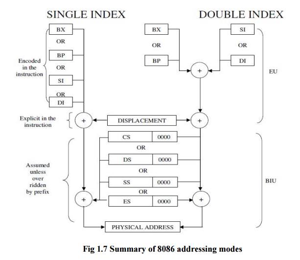
Addressing Modes
The 8086 has 12 addressing modes can be classified into five groups.
· Addressing modes for accessing immediate and register data (register and immediate modes).
· Addressing modes for accessing data in memory (memory modes)
· Addressing modes for accessing I/O ports (I/O modes)
· Relative addressing mode
· Implied addressing mode
ü Immediate addressing mode:
In this mode, 8 or 16 bit data can be specified as part of the instruction - OP Code Immediate Operand
Example 1: MOV CL, 03 H:Moves the 8 bit data 03 H into CL Example 2: MOV DX, 0525 H: Moves the 16 bit data 0525 H into DX
In the above two examples, the source operand is in immediate mode and the destination operand is in register mode.
A constant such as “VALUE” can be defined by the assembler EQUATE directive such as VALUE EQU 35H
Example: MOV BH, VALUE Used to load 35 H into BH
ü Register addressing mode:
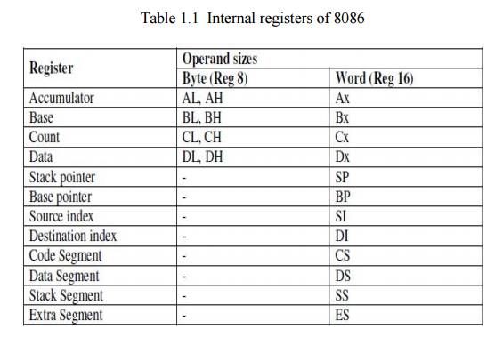
The operand to be accessed is specified as residing in an internal register of 8086. Table 1.1 below shows internal registers, anyone can be used as a source or destination operand, however only the data registers can be accessed as either a byte or word.
Example 1: MOV DX (Destination Register) , CX (Source Register)
Which moves 16 bit content of CS into DX.
Example 2: MOV CL, DL
Moves 8 bit contents of DL into CL
MOV BX, CH is an illegal instruction.
* The register sizes must be the same.
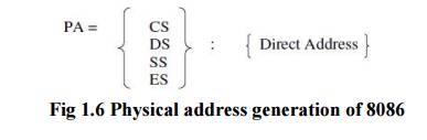
ü Direct addressing mode:
The instruction Opcode is followed by an affective address, this effective address is directly used as the 16 bit offset of the storage location of the operand from the location specified by the current value in the selected segment register. The default segment is always DS.
The 20 bit physical address of the operand in memory is normally obtained as PA = DS: EA
But by using a segment override prefix (SOP) in the instruction, any of the four segment registers can be referenced,
The Execution Unit (EU) has direct access to all registers and data for register and immediate operands. However the EU cannot directly access the memory operands. It must use the BIU, in order to access memory operands.
In the direct addressing mode, the 16 bit effective address (EA) is taken directly from the
displacement field of the instruction. Example 1: MOV CX, START
If the 16 bit value assigned to the offset START by the programmer using an assembler pseudo instruction such as DW is 0040 and [DS] = 3050. Then BIU generates the 20 bit physical address 30540 H.
The content of 30540 is moved to CL The content of 30541 is moved to CH Example 2: MOV CH, START
If [DS] = 3050 and START = 0040
8 bit content of memory location 30540 is moved to CH. Example 3: MOV START, BX
With [DS] = 3050, the value of START is 0040. Physical address: 30540
MOV instruction moves (BL) and (BH) to locations 30540 and 30541 respectively.
ü Register indirect addressing mode:
The EA is specified in either pointer (BX) register or an index (SI or DI) register. The 20 bit physical address is computed using DS and EA.
Example: MOV [DI], BX register indirect
If [DS] = 5004, [DI] = 0020, [Bx] = 2456 PA=50060.
The content of BX(2456) is moved to memory locations 50060 H and 50061 H.

when memory is accessed PA is computed from BX and DS when the stack is accessed PA is computed from BP and SS.
Example: MOV AL, START [BX] or
MOV AL, [START + BX] based mode
EA: [START] + [BX]
PA: [DS] + [EA]
The 8 bit content of this memory location is moved to AL.
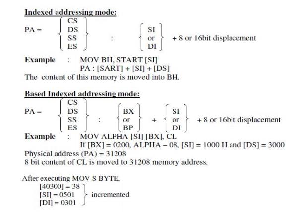
ü String addressing mode:
The string instructions automatically assume SI to point to the first byte or word of the source operand and DI to point to the first byte or word of the destination operand. The contents of SI and DI are automatically incremented (by clearing DF to 0 by CLD instruction) to point to the next byte or word.
Example: MOV S BYTE
If [DF] = 0, [DS] = 2000 H, [SI] = 0500, [ES] = 4000, [DI] = 0300
Source address: 20500, assume it contains 38 PA: [DS] + [SI]
Destination address: [ES] + [DI] = 40300, assume it contains 45
ü I/O mode (direct):
Port number is an 8 bit immediate operand. Example: OUT 05 H, AL
Outputs [AL] to 8 bit port 05 H
I/O mode (indirect):
The port number is taken from DX. Example 1: IN AL, DX
If [DX] = 5040
8 bit content by port 5040 is moved into AL. Example 2: IN AX, DX
Inputs 8 bit content of ports 5040 and 5041 into AL and AH respectively.
ü Relative addressing mode:
Example: JNC START
If CY=O, then PC is loaded with current PC contents plus 8 bit signed value of
START,
otherwise the next instruction is executed.
ü Implied addressing mode:
Instruction using this mode have no operands. Example: CLC which clears carry flag to zero.