The method of filter design by impulse invariance suffers from aliasing. Hence in order to overcome this drawback Bilinear transformation method is designed. In analogue domain frequency axis is an infinitely long straight line while sampled data z plane it is unit circle radius. The bilinear transformation is the method of squashing the infinite straight analog frequency axis so that it becomes finite.
Important Features of Bilinear Transform Method are
1. Bilinear transformation method (BZT) is a mapping from analog S plane to digital Z plane. This conversion maps analog poles to digital poles and analog zeros to digital zeros. Thus all poles and zeros are mapped.
2. This transformation is basically based on a numerical integration techniques used to simulate an integrator of analog filter.
3. There is one to one correspondence between continuous time and discrete time frequency points. Entire range in Ω is mapped only once into the range -∏≤ω≤∏.
4. Frequency relationship is non-linear. Frequency warping or frequency compression is due to non-linearity. Frequency warping means amplitude response of digital filter is expanded at the lower frequencies and compressed at the higher frequencies in comparison of the analog filter.
5. But the main disadvantage of frequency warping is that it does change the shape of the desired filter frequency response. In particular, it changes the shape of the transition bands.
CONVERSION OF ANALOG FILTER INTO DIGITAL FILTER
Z is represented as rejω in polar form and relationship between Z plane and S plane in BZT method is given as
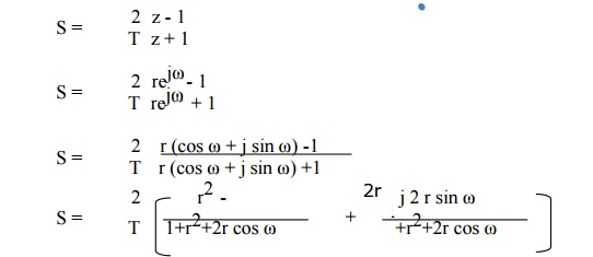
Comparing the above equation with S= σ + j Ω. We have
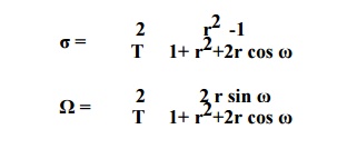
Here we have three condition
1. If σ < 0 then 0 < r < 1
2. If σ > 0 then r > 1
3. If σ = 0 then r=1
When r =1
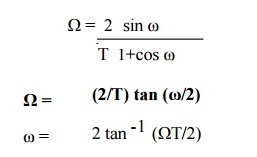
The above equations shows that in BZT frequency relationship is non-linear. The frequency relationship is plotted as
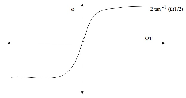
FIG - MAPPING BETWEEN FREQUENCY VARIABLE ω AND Ω IN BZT METHOD.
DIFFERENCE - IMPULSE INVARIANCE Vs BILINEAR TRANSFORMATION
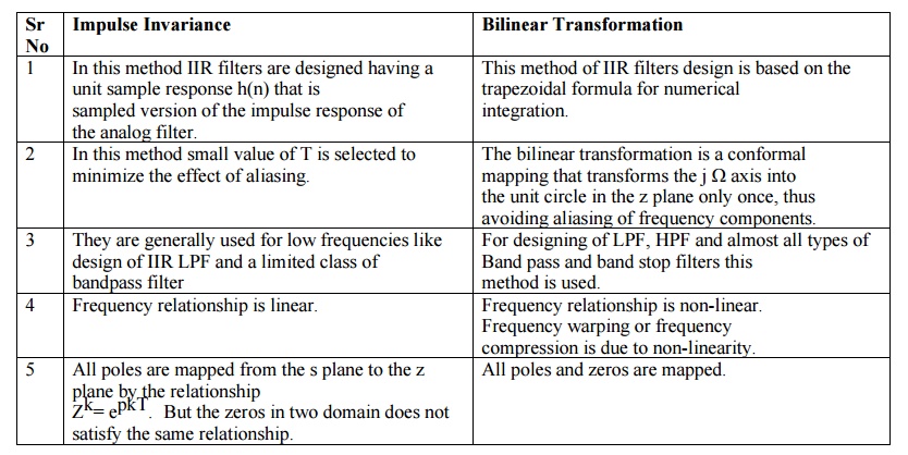
Impulse Invariance
1. In this method IIR filters are designed having a unit sample response h(n) that is sampled version of the impulse response of the analog filter.
2. In this method small value of T is selected to minimize the effect of aliasing.
3. They are generally used for low frequencies like design of IIR LPF and a limited class of bandpass filter
4. Frequency relationship is linear.
5. All poles are mapped from the s plane to the z plane by the relationship Zk= epkT. But the zeros in two domain does not satisfy the same relationship.
Bilinear Transformation
1. This method of IIR filters design is based on the trapezoidal formula for numerical integration.
2. The bilinear transformation is a conformal mapping that transforms the j Ω axis into the unit circle in the z plane only once, thus avoiding aliasing of frequency components.
3. For designing of LPF, HPF and almost all types of Band pass and band stop filters this method is used.
4. Frequency relationship is non-linear. Frequency warping or frequency compression is due to non-linearity.
5. All poles and zeros are mapped.
LPF AND HPF ANALOG BUTTERWORTH FILTER TRANSFER FUNCTION