
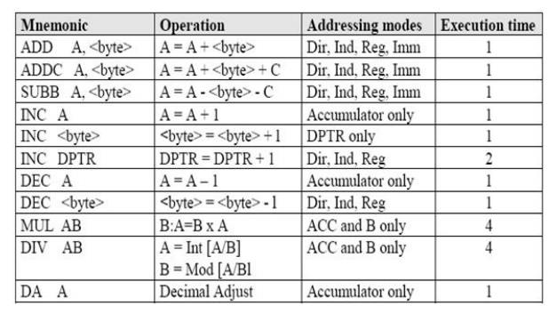
1 Arithmetic Instructions
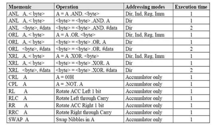
2 Logical Instructions
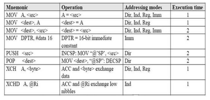
3 Data Transfer Instructions that access the Internal Data Memory
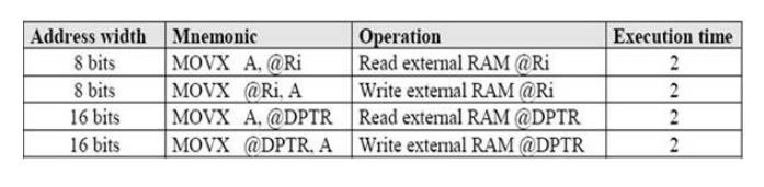
4 Data Transfer Instructions that access the External Data Memory
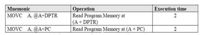
5 Look up Tables
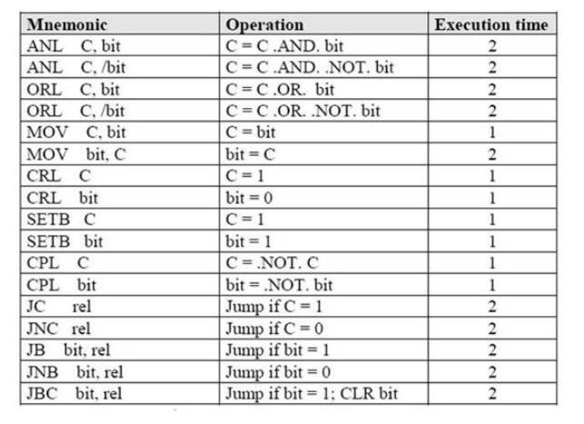
6 Boolean Instructions
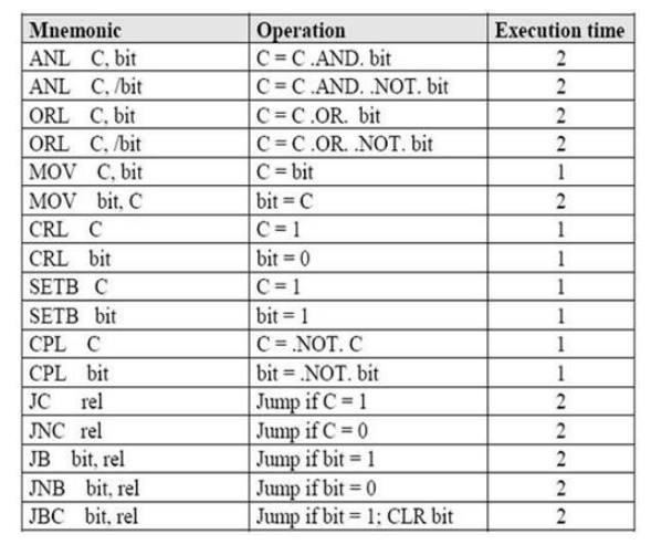
7 Jump Instructions
Program
Filename : pwm_servos.h
Hardware : Controller -> P89V51RD2
XTAL -> 18.432 MHz
Mode -> 6 Clock/MC
I/O : P1.4 -> Left (PWM-CEX1)
P1.5 -> Right (PWM-CEX2)
Compiler : SDCC
/* Control the Left servo */
void ServoL_back()
{
CCAP1H = 243;
}
void ServoL_forward()
{
CCAP1H = 230;
}
void ServoL_stop()
{
CCAP1H = 0;
}
/* Control the Right servo */ void ServoR_back()
{
CCAP2H = 230;
}
void ServoR_forward()
{
CCAP2H = 243;
}
void ServoR_stop()
{
CCAP2H = 0;
}
/* Initialize the PCA and PWM mode */ void Servos_init()
{
/* Initial Timer0 Generate Overflow PCA */
TMOD = 0x02; /* Timer0 Mode2 : 8bit auto reload */
TH0 = 16; /* 256-240, 8.125usec Auto-relead (20msec/PWM) */ TL0 = TH0; TCON = 0x10; /* setb TR0, TCON or 0001,0000*/
/*Initial PWM Period = 20mS (18.432MHz /6-Cycle Mode) Initial PCA Count From Timer0 Overflow 1 Cycle of Timer0 = (1/18.432MHz)x6 = 0.326uS Timer0 AutoReload = 240 Cycle = 78.125uS 1 Cycle PCA = [(1/18.432MHz)x6]x240 = 78.125uS Period 20mS of PCA = 20ms/78.125us = 256(CL Reload) CL(20mS) = 256 Cycle Auto Reload Load CCAPxH(1.0mS) = 256-13 = 243 (243,244,...,255 = 13 Cycle) Load CCAPxH(2.0mS) = 255-26 = 230 (230,231,...,255 = 26 Cycle)*/
CMOD=0x04; CCAPM1=0x42; CCAPM2=0x42; CCAP1H=0x00; CCAP2H=0x00; CCON=0x40;
}
test.c
#include <p89v51rd2.h> #include "pwm_servos.h" void PowerOn()
{
unsigned char inner, outer; IE = 0x00;
P1 = 0xFF; /* Motor STOP */
for (outer = 0x00; outer < 0x10; outer++) { /* Delay for a while */ for (inner = 0x00; inner < 0xFF; inner++);
}
Servos_init();
IE = 0x80; /* Start interrupt */
}
void main()
{
PowerOn();
ServoR_forward(); ServoL_back(); while (1);
}