STRUCTURES FOR FIR SYSTEMS
FIR Systems are represented in four different ways
1. Direct Form Structures
2. Cascade Form Structure
3. Frequency-Sampling Structures
4. Lattice structures.
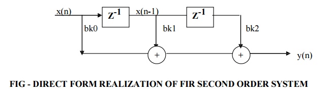
DIRECT FORM STRUCTURE OF FIR SYSTEM
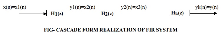
The convolution of h(n) and x(n) for FIR systems can be written
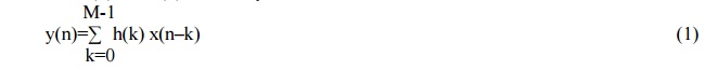
The above equation can be expanded as,
Y(n)= h(0) x(n) + h(1) x(n-1) + h(2) x(n-2) + …………… + h(M-1) x(n-M+1) (2)
Implementation of direct form structure of FIR filter is based upon the above equation.
1. There are M-1 unit delay blocks. One unit delay block requires one memory location.
Hence direct form structure requires M-1 memory locations.
2. The multiplication of h(k) and x(n-k) is performed for 0 to M-1 terms. Hence M multiplications and M-1 additions are required.
3. Direct form structure is often called as transversal or tapped delay line filter.
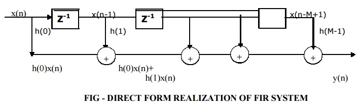
CASCADE FORM STRUCTURE OF FIR SYSTEM
In cascade form, stages are cascaded (connected) in series. The output of one system is input to another. Thus total K number of stages are cascaded. The total system function 'H' is given by
H= H1(z) . H2(z)……………………. Hk(z) (1)
H= Y1(z)/X1(z). Y2(z)/X2(z). ……………Yk(z)/Xk(z) (2)
Each H1(z), H2(z)… etc is a second order section and it is realized by the direct form as shown in below figure.
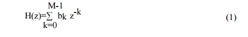
System function for FIR systems
Expanding the above terms we have
H(z)= H1(z) . H2(z)……………………. Hk(z)