
TM and TE wave between parallel plates
Parallel Plate Waveguide
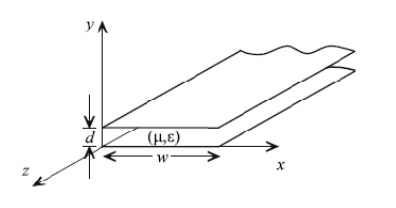
The parallel plate waveguide is formed by two conducting plates of width w separated by a distance d as shown below. This “waveguide” can support TEM, TE and TM modes.
The following assumptions are made in the determination of the various modes on the parallel plate waveguide:
(1)The waveguide is infinite in length (no reflections).
(2)The waveguide conductors are PEC’s and the dielectric is lossless.
(3) The plate width is much larger than the plate separation (w >> d) so that the variation of the fields with respect to x may be neglected.
Parallel Plate Waveguide TEM Mode
We have previously shown that the transverse fields of the TEM mode on a general wave guiding structure are equal to the corresponding static fields of the structure. The electrostatic field of the parallel plate waveguide (w >> d) is equivalent to that found in the ideal parallel plate capacitor.
Transmission Lines and Waveguides
Given a particular conductor geometry for a transmission line or waveguide, only certain patterns of electric and magnetic fields (modes) can exist for propagating waves. These codes must be solutions to the governing differential equation (wave equation) while satisfying the appropriate boundary conditions for the fields.
Transmission line
• Two or more conductors (two wire, coaxial, etc.).
• Can define a unique current and voltage and characteristic impedance along the line (use circuit equations).
Waveguide
• Typically one enclosed conductor (rectangular, circular, etc.).
• Cannot define a unique voltage and current along the waveguide (must use field equations.)
The propagating modes along the transmission line or waveguide may be classified according to which field components are present or not present in the wave. The field components in the direction of wave propagation are defined as longitudinal components while those perpendicular to the direction of propagation are defined as transverse components.
Assuming the transmission line or waveguide is oriented with its axis along the z-axis (direction of wave propagation), the modes may be classified as
(1) Transverse electromagnetic (TEM) modes - the electric and magnetic fields are transverse to the direction of wave propagation with no longitudinal components [Ez = Hz = 0]. TEM modes cannot exist on single conductor guiding structures. TEM modes are sometimes calledtransmission line modes since they are the dominant modes on transmission lines. Plane waves can also be classified as TEM modes. Quasi-TEM modes - modes which approximate true TEM modes when the frequency is sufficiently small.
(2) Transverse electric (TE) modes - the electric field is transverse to the direction of propagation (no longitudinal electric field component) while the magnetic field has both transverse and longitudinal components [Ez = 0, Hz . 0].
(3) Transverse magnetic (TM) modes - the magnetic field is transverse to the direction of propagation (no longitudinal magnetic field component) while the electric field has both transverse and longitudinal components [Hz = 0, Ez . 0].
TE and TM modes are commonly referred to as waveguide modes since they are the only modes which can exist in an enclosed guiding structure. TE and TM modes are characterized by a cutoff frequency below which they do not propagate. TE and TM modes can exist on transmission lines but are generally undesirable. Transmission lines are typically operated at frequencies below the cutoff frequencies of TE and TM modes so that only the TEM mode exists.
(4) Hybrid modes (EH or HE modes) - both the electric andmagnetic fields have longitudinal components [Hz . 0, Ez . 0]. The longitudinal electric field is dominant in the EH mode while the longitudinal magnetic field is dominant in the HE mode. Hybrid modes are commonly found in waveguides with inhomogeneous dielectrics and optical fibers.