
DC MOTOR
The major factors in selecting an actuator for mechatronic applications are
• Precision
• Accuracy and resolution
• Power required for actuation
• Cost of the actuation device
The most popular actuators in mechatronic systems are direct current ( DC) motors. DC motors are electromechanical devices that provide precise and continuous control of speed over a wide range of operations by varying the voltage applied to the motor.
The DC motor is the earliest form of electric motor. The desirable features of DC motors are their high torque, speed control ability over a wide range, speed-torque characteristics, and usefulness in various types of control applications.
DC motors are well suited for many applications, including manufacturing equipment, computer numerically controlled systems, servo valve actuators, tape transport mechanisms, and industrial robots.
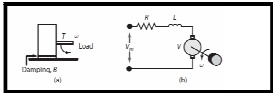
Mathematical Model of a DC Motor
The behavior of DC motors can be explained by two fundamental equations. These equations are known as torque and voltage equations. equations, respectively.
Torque equation: T = kti (4- 1) Voltage equation V = ke u: (4 -2)
where
T motor torque in N-m (newton-meters)
V induced voltage in V (volts)
i current in the armature circuit in A (amperes) kt torque constant in Nm/A
ke voltage constant in V/(rad /sec
DC motors are capable of producing high rotational velocities and comparatively low torque.
When the DC motors are used as actuators, a gearing arrangement is normally utilized to account for decreased speed and increased torque.
DC motors provide torque which is proportional to the armature current. A DC source capable of supplying positive and negative currents is normally used in practice. A generally used arrangement of the DC motor is through D C coupled push-pull amplifiers.
The selection of the DC moto r depends upon its application. DC servo motors are used in numerically controlled machine tools and robot manipulators
DC MOTOR
PRINCIPLE AND WORKING
The principle of working of a DC motor is that "when a current carrying conductor is placed in a magnetic field, it experiences a mechanical force". The direction of this force is given by Fleming's left hand rule and it's magnitude is given by F = magnetic flux density (B) * current (I) * length (L).
When armature windings are connected to DC supply, current sets up in the winding. Magnetic field may be provided by field winding (electromagnetism) or by using permanent magnets. In this case, current carrying armature conductors experience force due to the magnetic field, according to the principle stated above.
Commutator is made segmented to achieve unidirectional torque. Otherwise, the direction of force would have reversed every time when the direction of movement of conductor is reversed the magnetic field.
When the armature of the motor is rotating, the conductors also are cutting the magnetic flux lines and hence according to the Faraday's law of electromagnetic induction, emf induces in the armature conductors. And the direction of this induced emf is such that it opposes armature current (Ia) . The circuit diagram below illustrates the direction of the back emf and armature current.
Magnitude of Back emf can be given by the emf equation of DC generator.
CONSTRUCTION
The magnetic field is produced by the permanent magnet and it forms the stator. The coil of wire act as the rotor . In conventional D.C motor , several coils of wire are mounted is slots on a cylinder of magnetic material called armature .
The armature is mounted on bearing and is free to rotate. It is connected to source of D.C current through a switch mounted on the shaft and it's called as commutator.
CLASSIFICATION OF GENERATORS
Self- excited generators are classed according to the type of field connection they use.
There are three general types of field connections - SERIES - WOUND, SHUNT - WOUND (parallel), and COMPOUND - WOUND.
Compound - wound generators are further classified as cumulative - compound and differential - compound.
Series - Wound Generator or Series connected generator
In the series - wound generator, the field windings are connected in series with the armature.
Current that flows in the armature flows through the external circuit and through the field windings.
The external circuit connected to the generator is called the load circuit
Shunt - Wound Generators
In a shunt - wound generator, the field coils consist of many turns of small wire and relatively high field resistance.
They are connected in parallel with the load. In other words, they are connected across the output voltage of the armature.
Compound - Wound Generators
Compound- wound generators have a series - field winding in addition to a shunt -field winding.. The shunt and series windings are wound on the same pole pieces.