
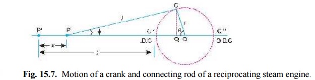
Fig. 15.7. Motion of a crank and connecting rod of a reciprocating steam engine.
Let l = Length of connecting rod between the centres,
r = Radius of crank or crank pin circle,
φ = Inclination of connecting rod to the line of stroke PO, and
n = Ratio of length of connecting rod to the radius of crank = l/r.
ANGULAR VELOCITY AND ACCELERATION OF THE CONNECTING ROD
Consider the motion of a connecting rod and a crank as shown in Fig. 15.7.From the geometry of the figure, we find that
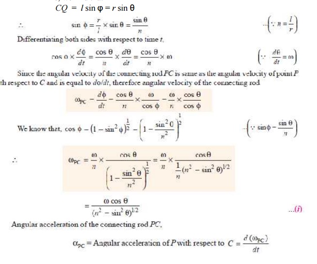
CQ = l sin φ = r sin θ
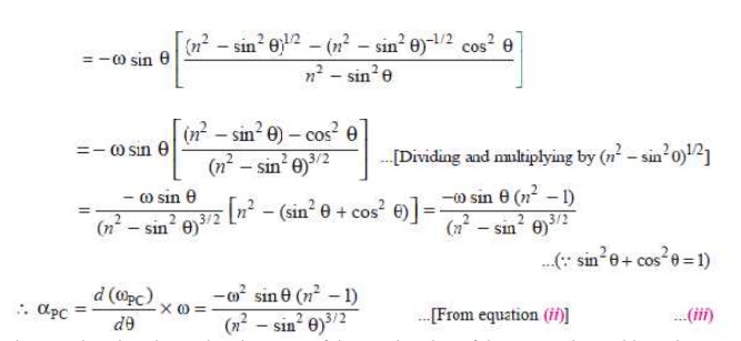
The negative sign shows that the sense of the acceleration of the connecting rod is such that it tends to reduce the angle φ..
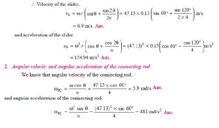
Q.In a slider crank mechanism, the length of the crank and connecting rod are 150 mm and 600 mm respectively. The crank position is 60° from inner dead centre. The crank shaft speed is 450 r.p.m. (clockwise). Using analytical method, determine: 1. Velocity and acceleration of the slider, and 2. Angular velocity and angular acceleration of the connecting rod.
Solution. Given : r = 150 mm = 0.15 m ; l = 600 mm = 0.6 m ; θ = 60°; N = 400 r.p.m or ω = π × 450/60 = 47.13 rad/s
1. Velocity and acceleration of the slider
We know that ratio of the length of connecting rod and crank,
n = l / r = 0.6 / 0.15 = 4
APPROXIMATE ANALYTICAL METHOD FOR VELOCITY AND ACCELERATION OF THE PISTON
Fig. 15.7. Motion of a crank and connecting rod of a reciprocating steam engine.
Let l = Length of connecting rod between the centres,
r = Radius of crank or crank pin circle,
φ = Inclination of connecting rod to the line of stroke PO, and
n = Ratio of length of connecting rod to the radius of crank = l/r.