
FREQUENCY RESPONSE CHARACTERISTIC
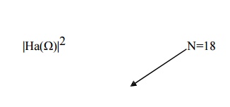
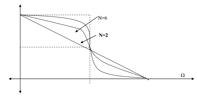
The frequency response characteristic of |Ha(Ω)|2 is as shown. As the order of the filter N increases, the butterworth filter characteristic is more close to the ideal characteristic. Thus at higher orders like N=16 the butterworth filter characteristic closely approximate ideal filter characteristic. Thus an infinite order filter (N ∞) is required to get ideal characteristic.
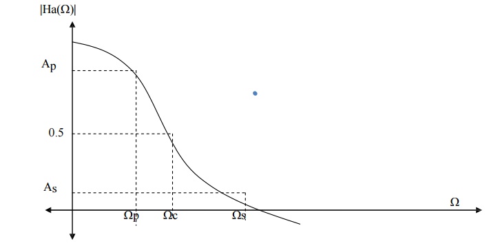
Ap= attenuation in passband.
As= attenuation in stopband.
Ωp = passband edge frequency
Ωs = stopband edge frequency
Specification for the filter is
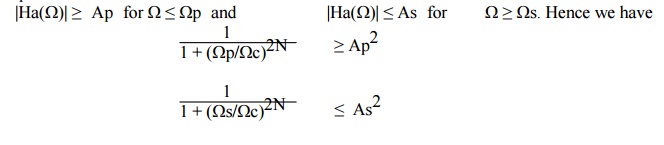
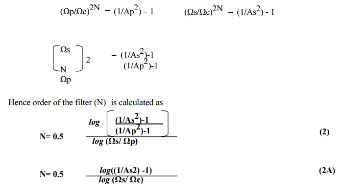
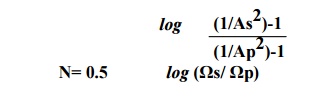
To determine the poles and order of analog filter consider equalities.
Q) Design a digital filter using a butterworth approximation by using impulse invariance.
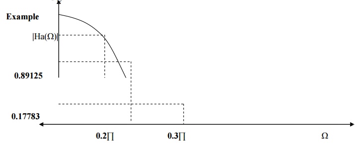
Filter Type - Low Pass Filter
Ap - 0.89125
As - 0.17783
Ωp - 0.2∏
Ωs - 0.3∏
Step 1) To convert specification to equivalent analog filter.
(In impulse invariance method frequency relationship is given as ω= Ω T while in Bilinear transformation method frequency relationship is given as Ω= (2/T) tan (ω/2) If Ts is not specified consider as 1)
|Ha(Ω)| ≥ 0.89125 for Ω ≤ 0.2∏/T and |Ha(Ω)| ≤ 0.17783 for Ω ≥ 0.3∏/T.
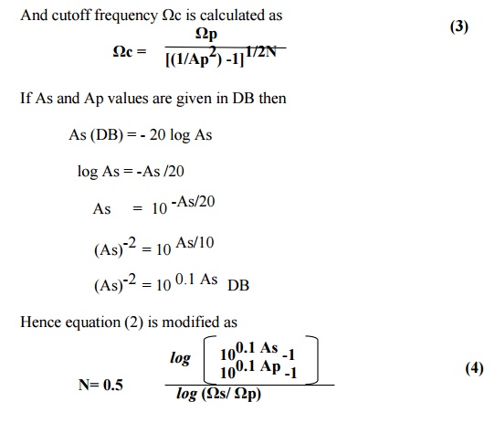
Step 2) To determine the order of the filter.
N= 5.88
1. Order of the filter should be integer.
2. Always go to nearest highest integer vale of N.
Hence N=6
Step 3) To find out the cutoff frequency (-3DB frequency)
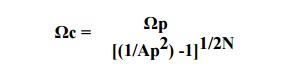
cutoff frequency Ωc = 0.7032
Step 4) To find out the poles of analog filter system function.
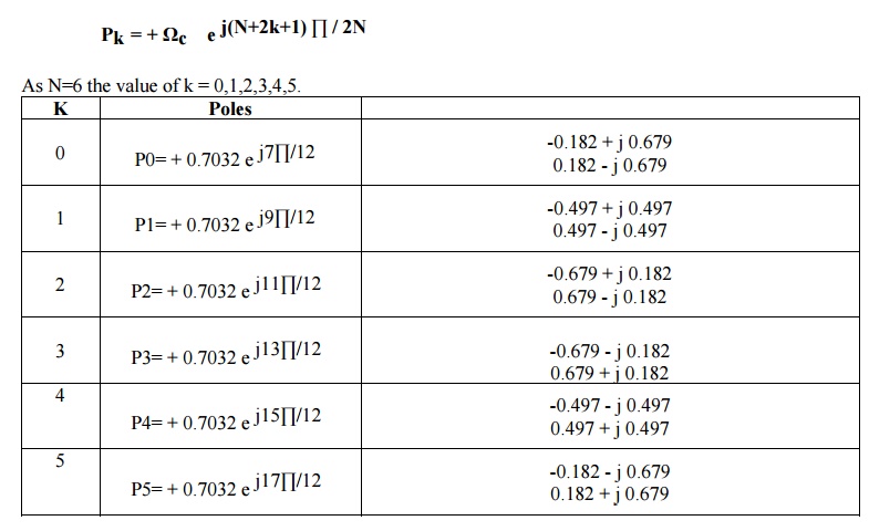
For stable filter all poles lying on the left side of s plane is selected. Hence
S1 = -0.182 + j 0.679 S1* = -0.182 - j 0.679
S2 = -0.497 + j 0.497 S2* = -0.497 - j 0.497
S3 = -0.679 + j 0.182 S3* = -0.679 - j 0.182
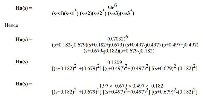
Step 5) To determine the system function (Analog Filter)
Step 6) To determine the system function (Digital Filter)
(In Bilinear transformation replace s by the term ((z-1)/(z+1)) and find out the transfer function of digital function)
Step 7) Represent system function in cascade form or parallel form if asked.
Q) Given for low pass butterworth filter
Ap= -1 db at 0.2∏
As= -15 db at 0.3∏
a) Calculate N and Pole location
b) Design digital filter using BZT method.
Q) Obtain transfer function of a lowpass digital filter meeting specifications
Cutoff 0-60Hz
Stopband > 85Hz
Stopband attenuation > 15 db
Sampling frequency= 256 Hz . use butterworth characteristic.
Q) Design second order low pass butterworth filter whose cutoff frequency is 1 kHz at sampling frequency of 104 sps. Use BZT and Butterworth approximation.