
FREQUENCY TRANSFORMATION
When the cutoff frequency Ωc of the low pass filter is equal to 1 then it is called normalized filter. Frequency transformation techniques are used to generate High pass filter, Bandpass and bandstop filter from the lowpass filter system function.
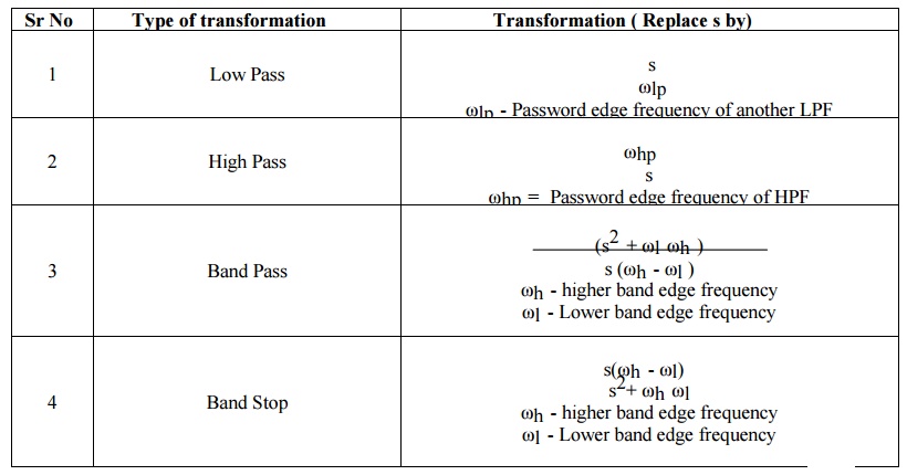
FREQUENCY TRANSFORMATION (ANALOG FILTER)
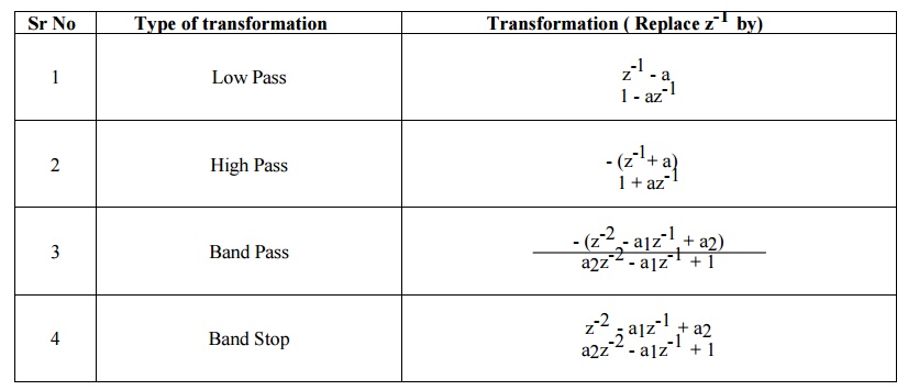
FREQUENCY TRANSFORMATION ((DIGITAL FILTER)
Example:
Q) Design high pass butterworth filter whose cutoff frequency is 30 Hz at sampling frequency of 150 Hz. Use BZT and Frequency transformation.
Step 1. To find the prewarp cutoff frequency
ωc* = tan (ωcTs/2) = 0.7265
Step 2. LPF to HPF transformation
For First order LPF transfer function H(s) = 1/(s+1) Scaled
transfer function H*(s) = H(s) |s=ωc*/s H*(s)= s/(s + 0.7265)
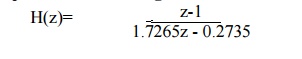
Step 3. Find out the digital filter transfer function. Replace s by (z-1)/(z+1)
Q) Design second order band pass butterworth filter whose passband of 200 Hz and 300 Hz and sampling frequency is 2000 Hz. Use BZT and Frequency transformation.
Q) Design second order band pass butterworth filter which meet following specification Lower cutoff frequency = 210 Hz
Upper cutoff frequency = 330 Hz Sampling Frequency = 960 sps
Use BZT and Frequency transformation.